

Module 2: Template Design
 ShareCompartir
Note: Although this software and accompanying documentation is dated 2004-2005, it is still valid in 2014. Questions can be sent to CDC-INFO.
This option abstracts three types of data from a 96-well ELISA plate: standards, unknowns, and quality control samples. This option gives the user a wide degree of latitude in creating template formats for this data abstraction. The main restriction involved with this operation is that samples must be arranged in rectangular arrays and like samples (replicates) must be contiguous.
The template file selection dialog window appears after selecting this module for processing from the main menu (Figure 3). All files with a .TPL extension will appear in the file list box. Select the file for processing and the template will be loaded for viewing and editing.
To create a new template, move the cursor to the File Name box in the template file selection dialog window. Erase all characters in this box and enter the word ‘NEW’ (without the quotes) and then click on OK. ELISA for Windows will respond with the default dialog window shown in Figure 7.
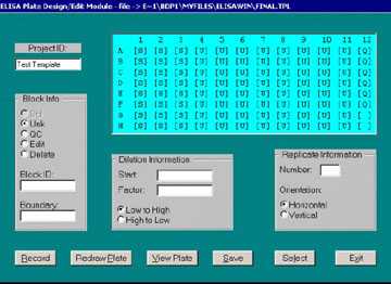
A schematic diagram for a blank plate is displayed along with several boxes to select options and input data. Through the use of these options a template may be designed from scratch or an existing template edited to produce a new template.
The ‘Project ID’ field allows users to assign a code to the template and may be used to group unknown samples under one study or project identification heading. This field is optional.
In the ‘Block Info’ box, the user may select one of three types of blocks, standard (Std), unknown (Unk), or quality control (QC). Additionally, the user may edit an existing block or delete a block. The Block ID is another optional mechanism used to assign a unique code to a particular block. As an example, this may be used to code unknowns within a particular project. All subsequent output dealing with the unknown specimens will be annotated with these unique identification codes.
To define a block, position the cursor within the brackets of the upper left cell and click with the left mouse button. An ‘X’ will appear within the brackets. Repeat this procedure for the lower right cell. Two ‘X’s will now indicate the opposing corners of the block. Select the type of block just outlined by clicking on ‘Std’, ‘Unk’, or ‘QC’ in the Block Info box. If desired, enter a Block ID. In the ‘Dilution Information’ box enter the starting dilution (Start) and the magnitude of change between the dilutions in the series (Factor). ELISA for Windows deals with reciprocal dilutions. Thus, if a series begins with a 1:600 dilution, 600 would be entered in the Start field. If the series follows a twofold dilution then ‘2’ would be entered in the Factor field. If the series proceeds in an ascending fashion (i.e., 1:600, 1:1200, 1:2400, etc), then select the ‘low to high’ option. If the series progresses in a descending order (i.e., 1:600, 1:300, 1:150, etc.), then select the ‘high to low’ option. This may seem backwards at first. The way to conceptualize these prompts is to think of the reciprocal dilution numbers. If there are three dilutions, 600 is less than 2400 so low to high means start at 600 and proceed through 2400. High to low is just the opposite: start with 600 and step down to 150.
In the ‘Replicate Information’ box the number of replicates and their orientation are selected. ELISA for Windows will check to make sure these responses are consistent with the block defined by the user. For example, a block defined as A1 -H3 contains eight rows and three columns. This allows for a replicate series running three across (horizontally) or eight down (vertically). Any other responses in these fields will be flagged as an error and the program will ask the user to reenter the required information.
Once all the information necessary to define a block is entered, clicking on the ‘Record’ command button will save the block definition for later recall and/or editing. The ‘Boundary’ field in the Block Info box will contain the coordinates for the upper left and lower right corner cells of the newly defined block. ELISA for Windows allows only one standards block per plate. After the standards block has been defined, the standards option button in the Block Info box will be inactivated. If an existing standards block is deleted, this option button will be reactivated.
Once a block’s information is recorded, the cells are filled in to indicate they are no longer free to be included in succeeding blocks. The cells within a standards block are indicated with an ‘S’; unknowns with a ‘U’; and quality control samples with a ‘Q’. If any block is subsequently deleted, the letters in the corresponding cells will be blanked out indicating the availability of the cells for future block definitions.
To delete a block, click on any cell within the block with the left mouse button. An ‘X’ will appear in the cell. Select the ‘Delete’ option in the Block Info box and click on the ‘Record’ command button. The cells in the block will be blanked out indicating the block has been deleted.
To recall a block’s defining parameters, click on any cell within the block with the left mouse button. An ‘X’ will appear in the cell. Click on the ‘Redraw Plate’ command button and the information previously entered for that block will be inserted into the appropriate entry fields. Once this information is retrieved, any part of it may be altered. Once the information has been edited, again, click on any cell within the block (confirmed with the placement of the ‘X’ in the cell) and select the ‘Edit’ option in the Block Info box. Finally click on the ‘Record’ button to register the change. To reset or blank out the data entry fields, click on the ‘Redraw Plate’ command button without first marking a cell in an existing block.
This technique may also be used to copy the contents of one block to another block. This is useful if several unknowns with identical defining parameters are being added to a plate. Once one unknown is established, its information may be recalled and used for any subsequent block’s definition. Once the information is inserted in the data entry fields, a new block may be defined by clicking on the opposing corner cells in the plate schematic diagram. Clicking on the ‘Record’ command button will then establish the new block using all the parameters from the block which was previously recalled. When applying this technique care must be taken to change the Block ID or this information will also be copied over to the new block. This is only necessary if each unknown requires a unique block identifier.
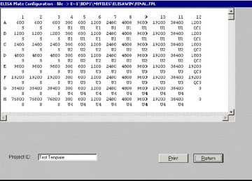
Clicking on the ‘View Plate’ command button will present an expanded view of the plate with each well defined with its dilution and block designation. Unknowns and quality control samples are numbered in the order in which they are defined. A sample display is shown in Figure 8. If the window is not large enough to contain the entire plate diagram, the scroll bars may be used to pan horizontally and vertically through the display. The block identifiers are listed under the plate diagram and may be viewed using the vertical scroll bar.
It is possible to create a block with a single point dilution. In this case, the user would block off the desired cells and enter the single dilution value in the ‘Start’ data entry field. Enter 1 in the ‘Factor’ data entry field. Finally, enter the necessary data in the Replicate Information box. If there are no replicates (a single point determination in a single well) then enter 1 for the number of replicates and ignore the orientation.
There is no limit to the number of blocks which may be assigned to any one plate with the proviso that there be only one block of standards.
When all blocks of information have been defined, clicking on the ‘Save’ command button will lead to the template file selection dialog box. The user will be prompted for a filename for the newly created template. A new file name may be specified or the old template file may be over-written and replaced. Retain the .TPL extension to insure the file name will appear in subsequent file name lists when this module is entered in the future. The program will return to the main menu (Figure 3) and the name of the template will appear in the descriptive box to the right of the option group on the opening menu screen when the template design option is selected.
This completes the template creation description. Once the template module is entered from the main menu, all template files will be listed in the file list box in the template file selection dialog window and the user may select the desired template for data processing. Once the selection is made, the formatted template will appear on screen in the context of the dialog window shown in Figure 7.
The ‘Select’ command button will choose the given template for subsequent processing in the data abstraction module. ‘View Plate’ allows the user to examine the chosen template checking the dilution settings within each block of standards, unknowns, and quality control samples. The various options in the Block Info box may be selected to add new blocks to existing templates, delete blocks from templates and change various parameters for any block. In this manner ELISA for Windows allows users to easily alter existing templates. These editing functions facilitate the creation of new templates that are only slightly different from existing ones without starting from the beginning with a blank template. These editing functions may also be used during the creation of templates to correct entry errors. If a user misspecifies one of the parameters within a block of standards, unknowns or quality control samples, the block may be edited or deleted and recreated. When a template is edited, the user will be given the opportunity to name the new template at the end of the procedure. A template file selection window appears with the original name of the template located in the file name box. Clicking on OK will store the changes in the original template file. The file name may be edited If the user does not wish to overwrite the existing template file.
Never assign a dilution <= 0.0 to any well, for standards, unknowns, or quality control samples. This will result in a fatal error when the concentration calculation module is entered. If dilutions <= 0.0 exist, ELISA for Windows will end with unpredictable results when calculating concentrations from optical densities associated with the dilutions.
In conclusion, each template is not required to contain blocks of wells representing all three data types. Users are free to create templates with any combination of standards, patient unknowns and quality control samples. The only restriction is that there may be only one block of standards per template. The Operational Qualification Protocol contains several examples illustrating the different options in this module.
Refer to Appendix B for a description of the template (.TPL) file format.
- Page last reviewed: September 4, 2013
- Page last updated: September 21, 2005
- Content source: