

Chapter 12 Figures
 ShareCompartir
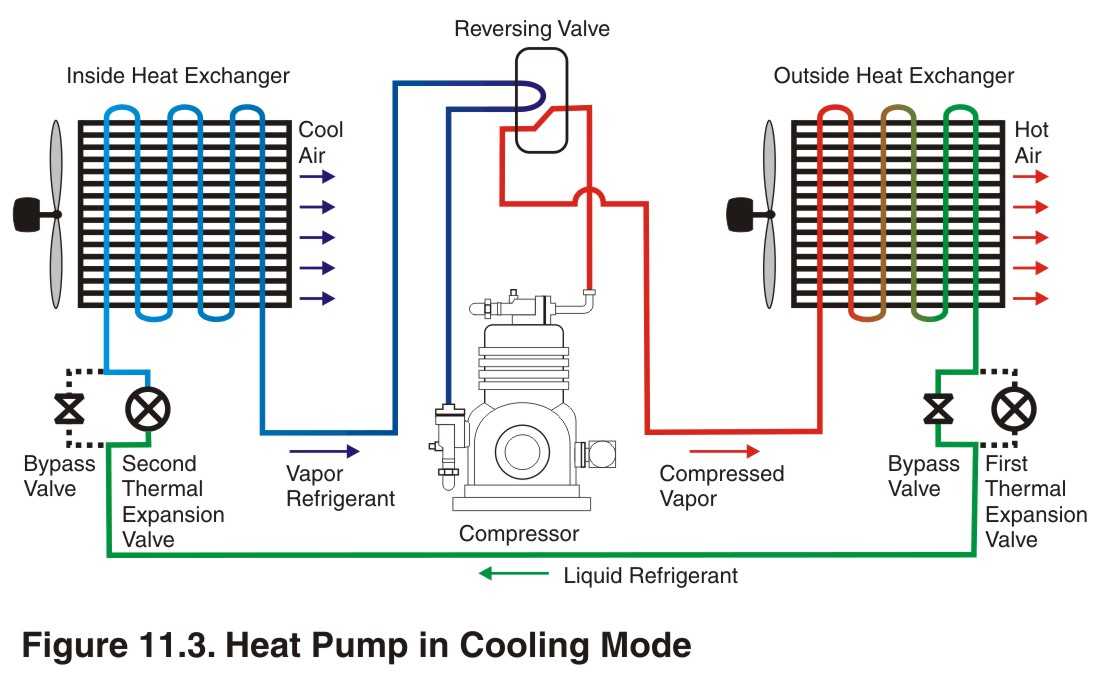
Figure 12.1.Piping Hookup for Inside Tank Installation
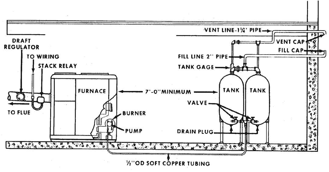
Figure 12.2. Piping Hookup for Buried Outside Tank
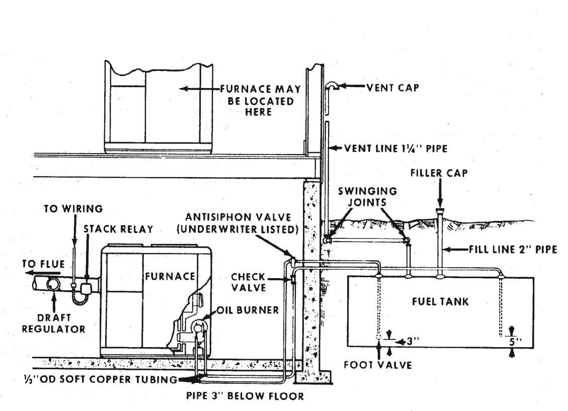
Figure 12.3. Heat Pump in Cooling Mode
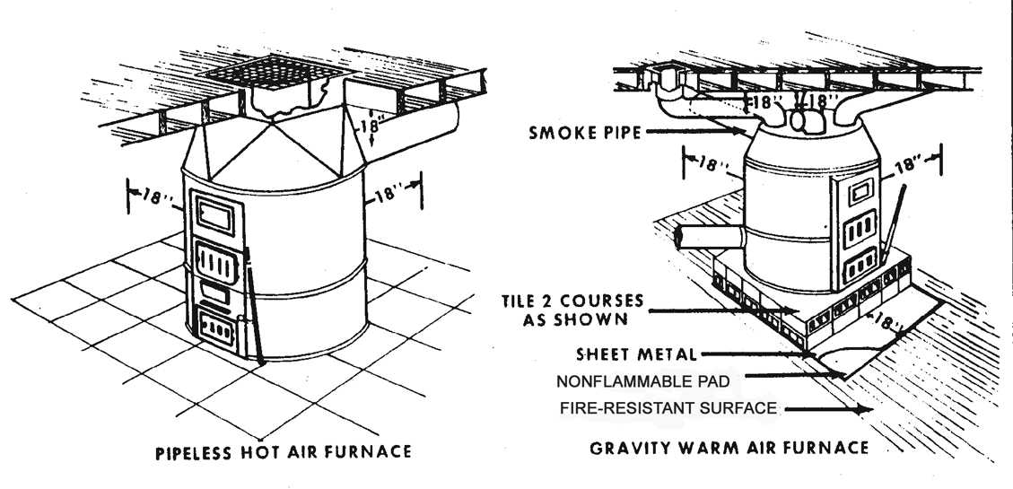
Figure 12.4. Minimum Clearance for Pipeless Hot Air and Gravity Warm Air Furnace
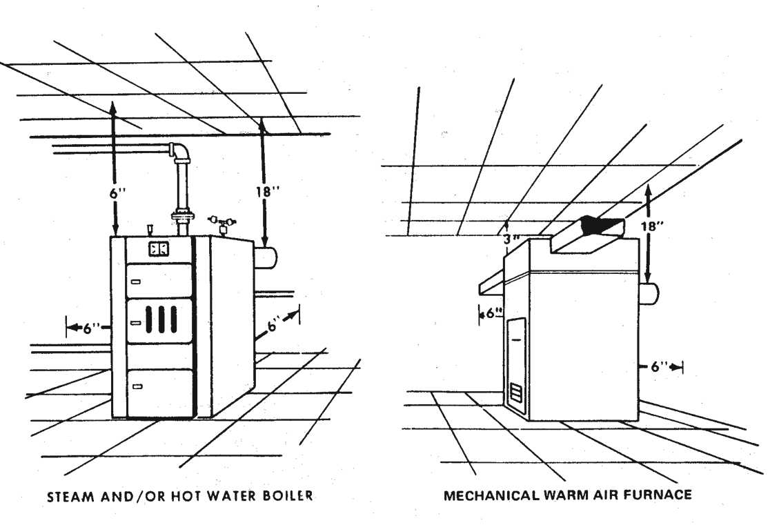
Figure 12.5. Minimum Clearance for Steam or Hot Water Boiler and Mechanical Warm-air Furnace
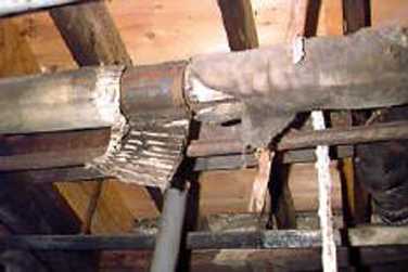
Figure 12.6. Heating Ducts Covered With Asbestos Insulation
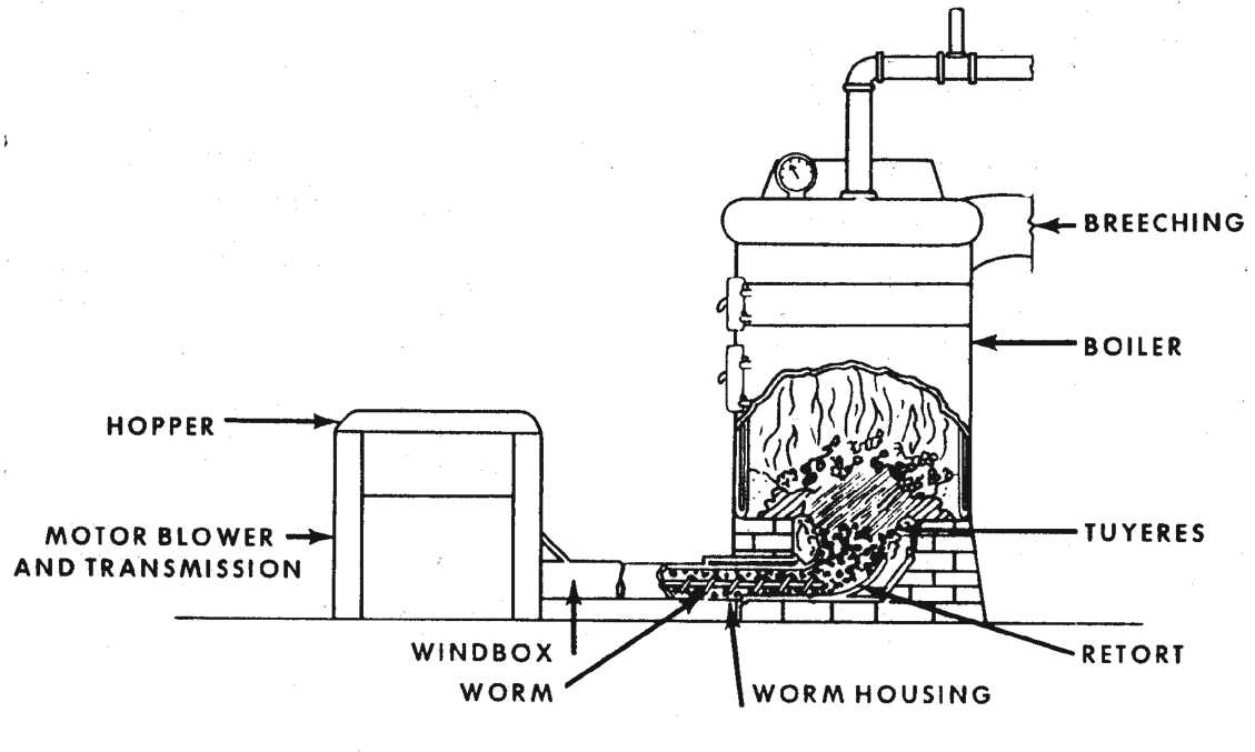
Figure 12.7. Typical Underfeed Coal Stoker Installation in Small Boilers
Figure 12.8. Cutaway View of Typical High-pressure Gun Burner
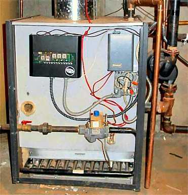
Figure 12.9. Gas-fired Boiler
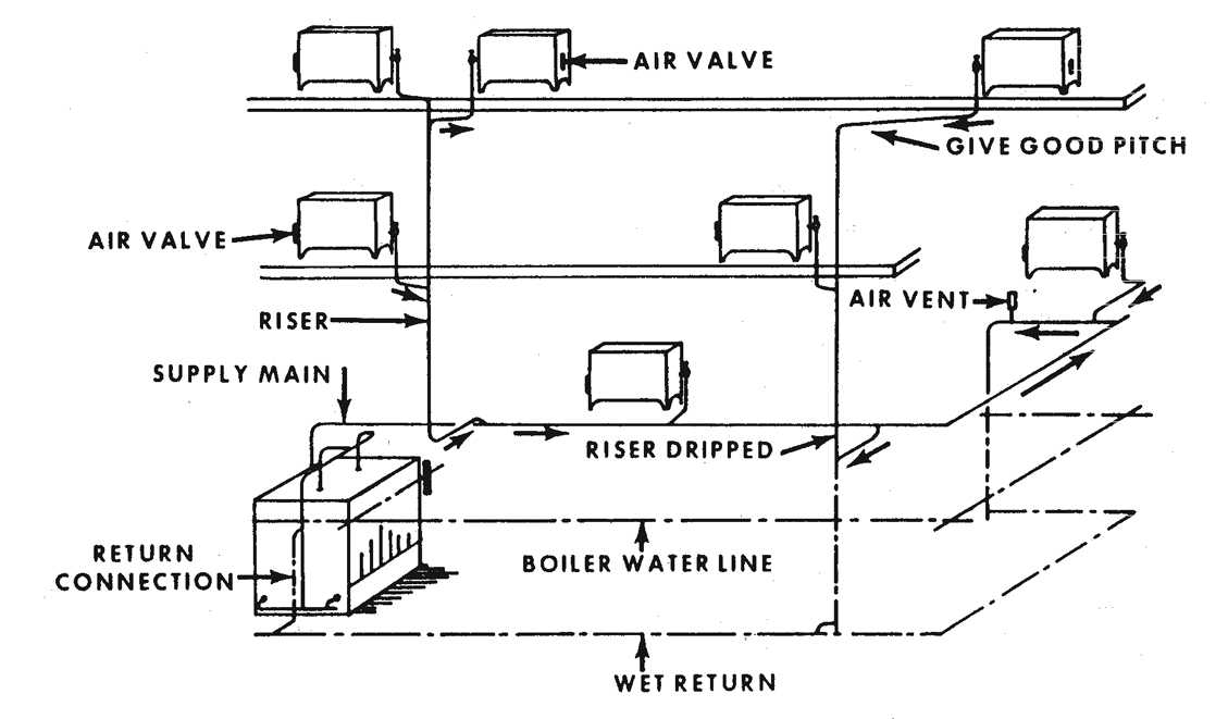
Figure 12.10. Typical Gravity One-pipe Heating System
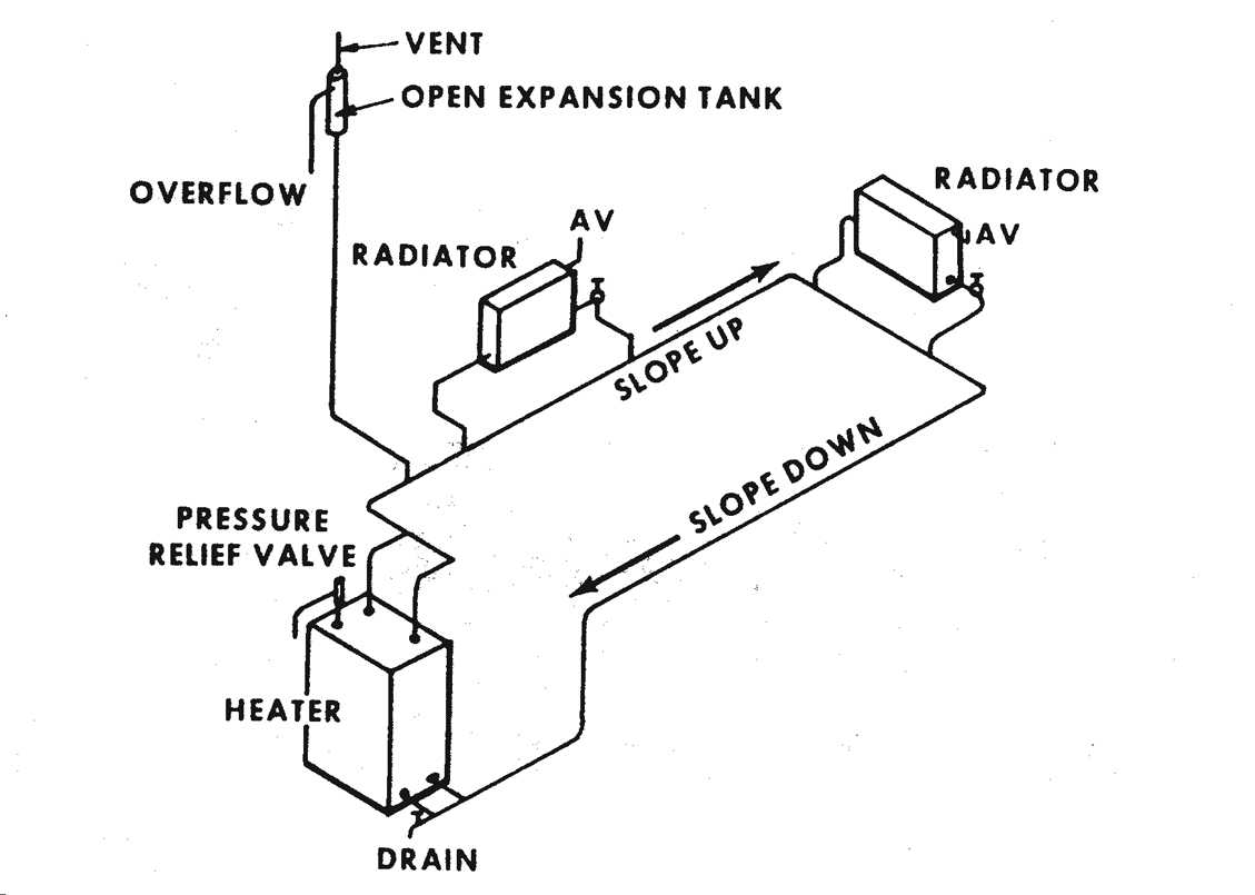
Figure 12.11. One-pipe Gravity Water Heating System
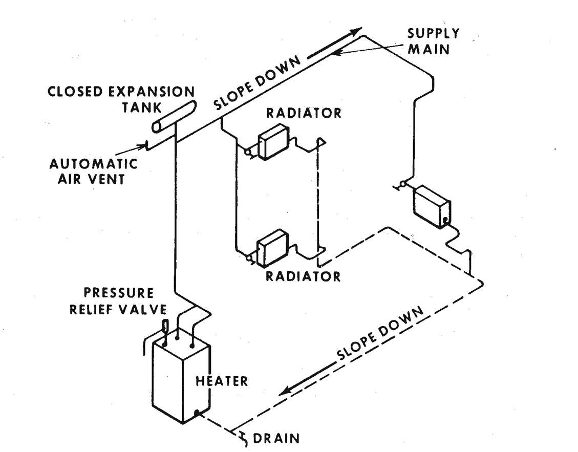
Figure 12.12. Two-pipe Gravity Water Heating System
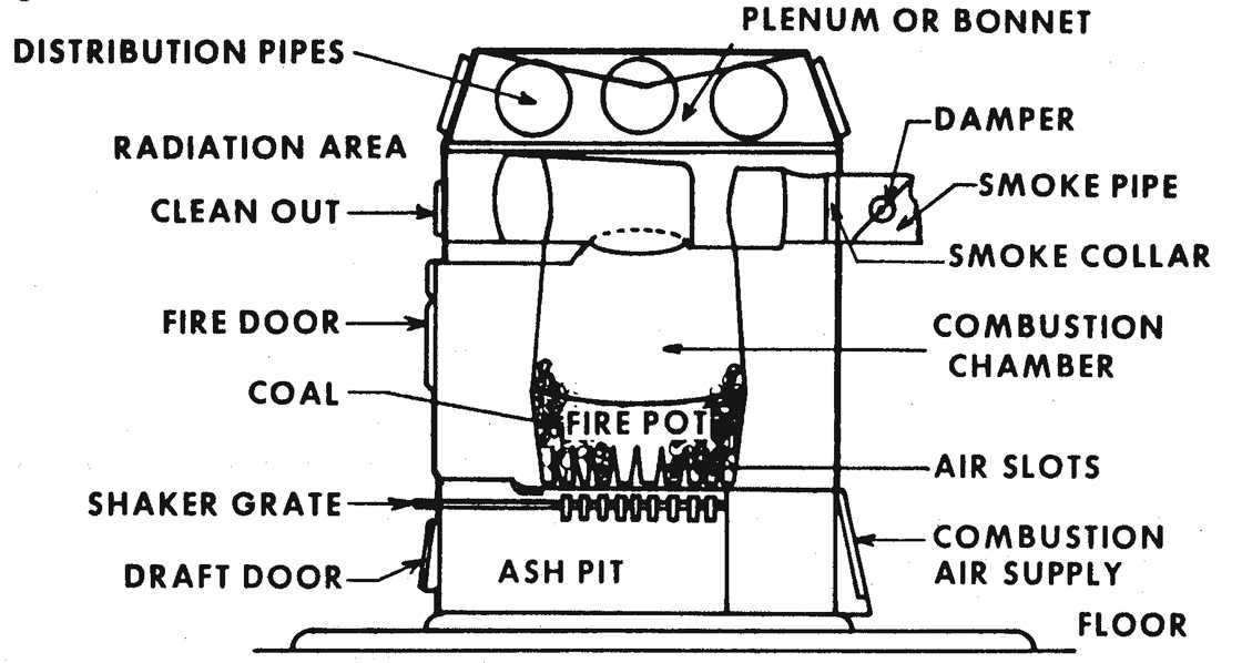
Figure 12.13. Warm-air Convection Furnace
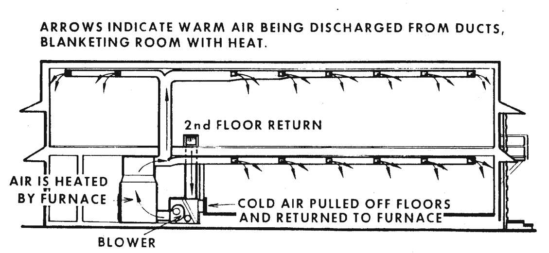
Figure 12.14. Cross-sectional View of Building Showing Forced-warm-air Heating System
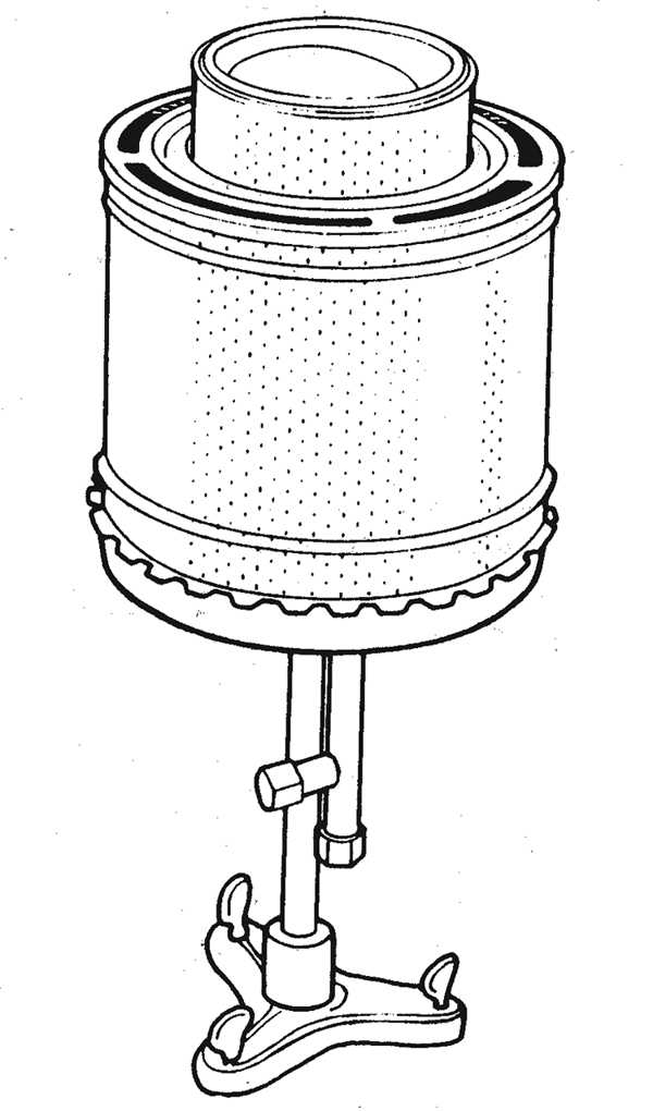
Figure 12.15. Perforated-sleeve Burner
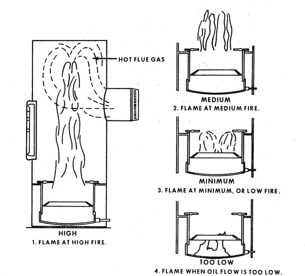
Figure 12.16. Condition of Burner Flame with Different Rates of Fuel Flow
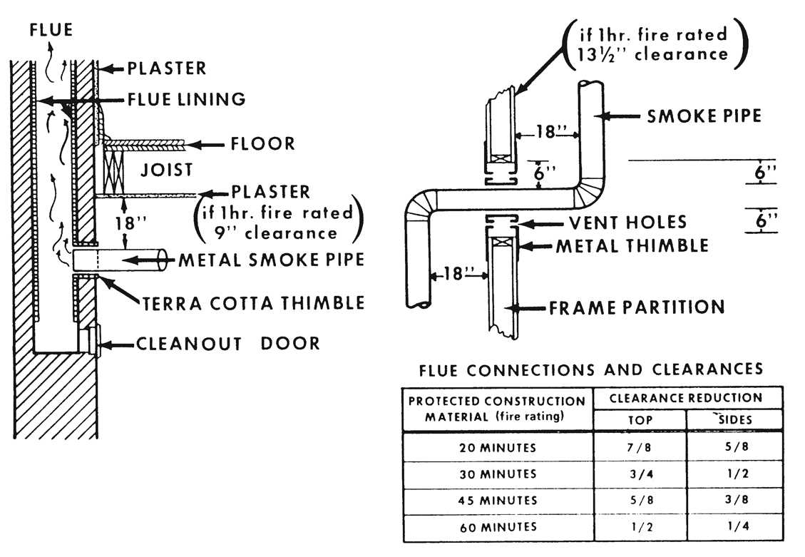
Figure 12.17. Wall and Ceiling Clearance Reduction
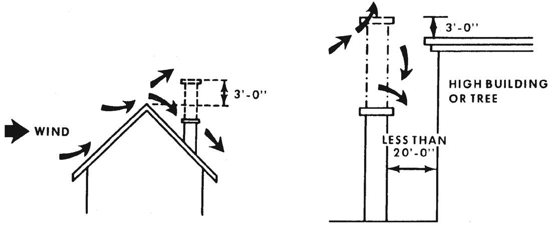
Figure 12.18. Draft in Relation to Height of Chimney
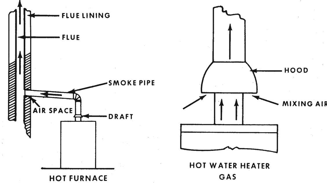
Figure 12.19. Location and Operation of Typical Backdraft Diverter
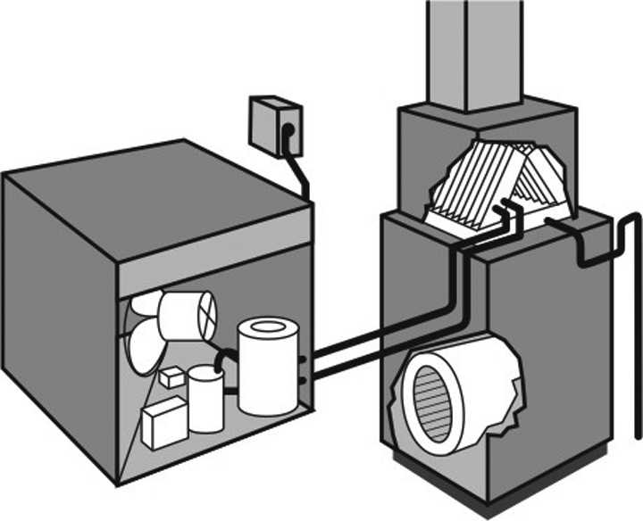
Figure 12.20. Split-system Air Conditioner
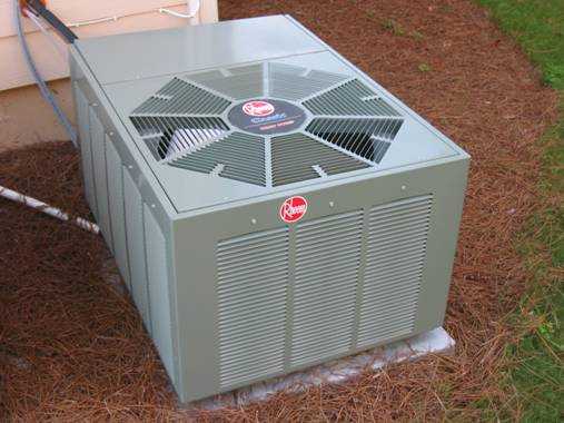
Figure 12.21. External Air-conditioning Condenser Unit
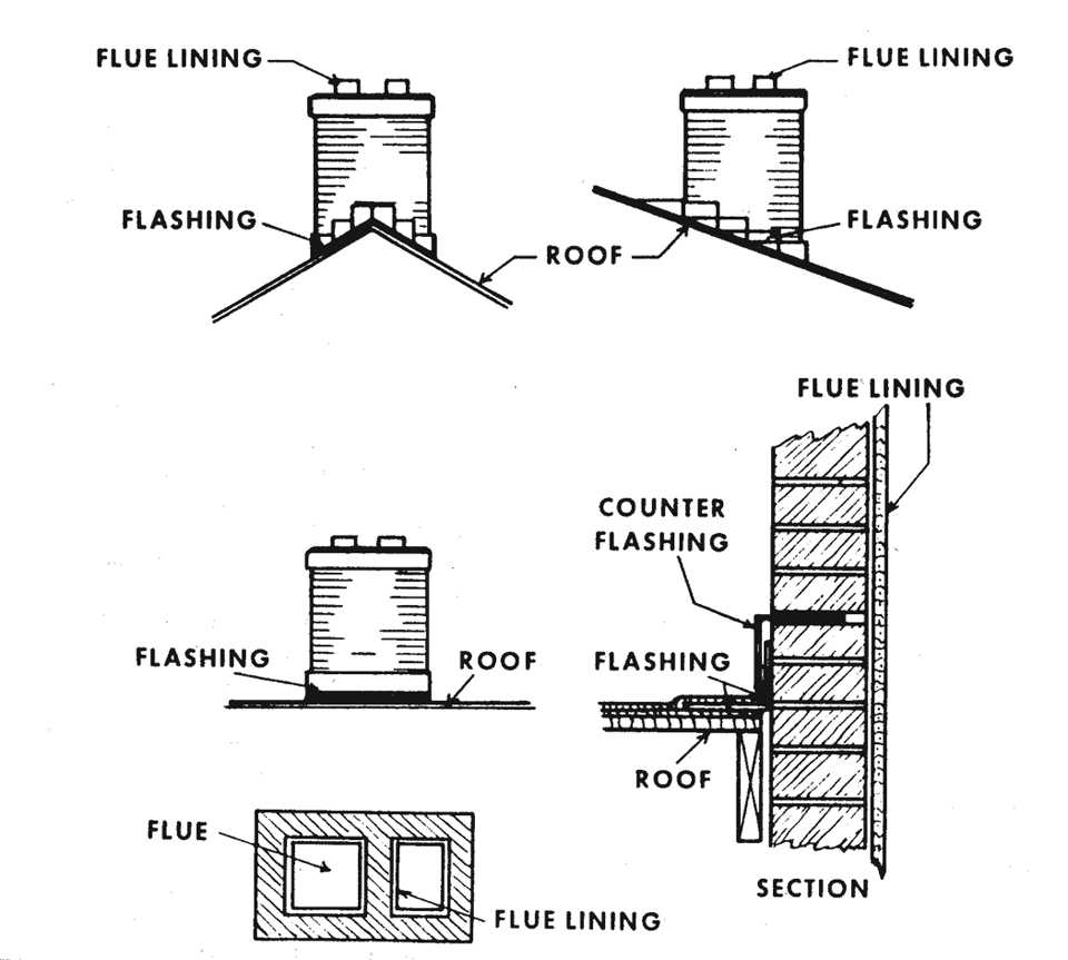
Figure 12.22. Chimney Plan
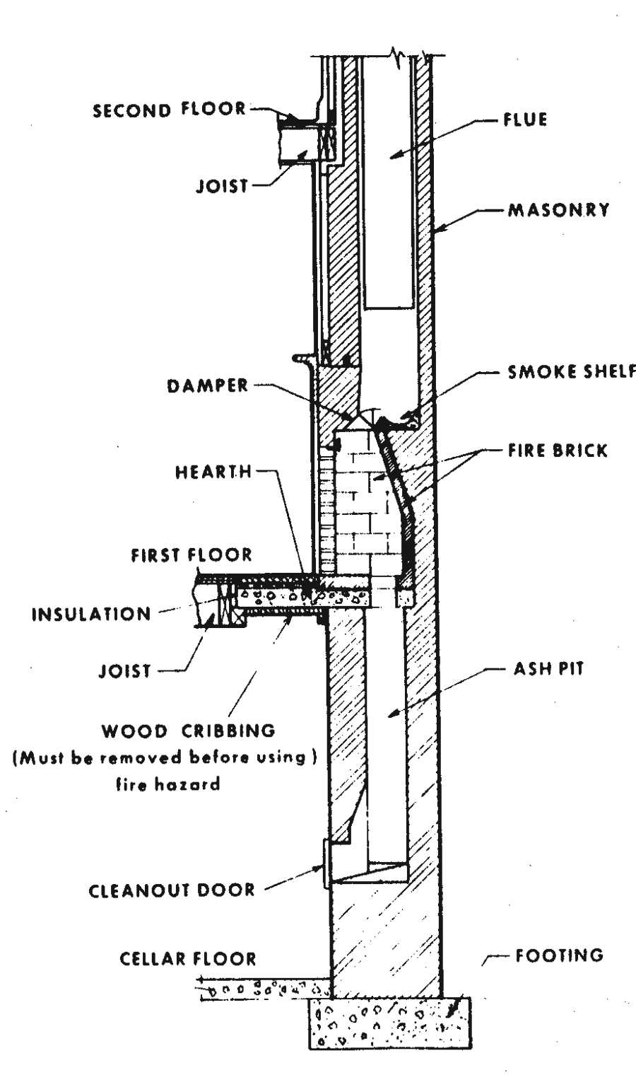
Figure 12.23. Fireplace Construction
- Page last reviewed: October 1, 2009
- Page last updated: December 8, 2009
- Content source: