

Chapter 11 Figures
 ShareCompartir
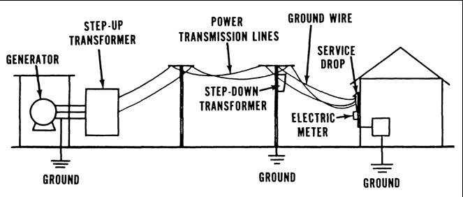
Figure 11.1. Utility Overview
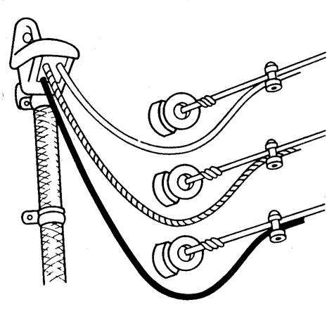
Figure 11.2. Entrance Head
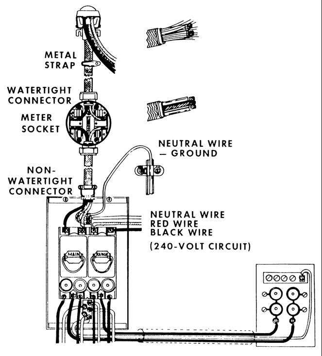
Figure 11.3. Armored Cable Service Entrance
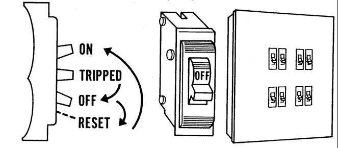
Figure 11.4. Breakers
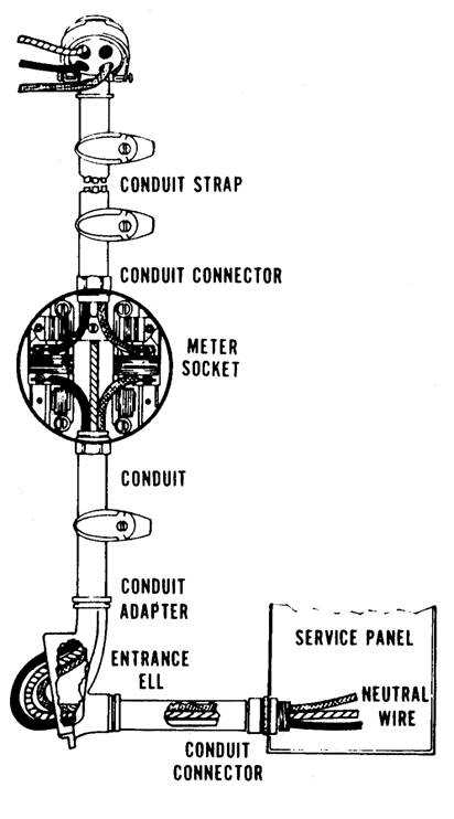
Figure 11.5. Thin-wall Conduit
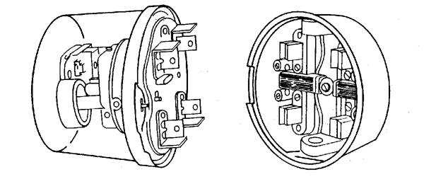
Figure 11.6. Electric Meter
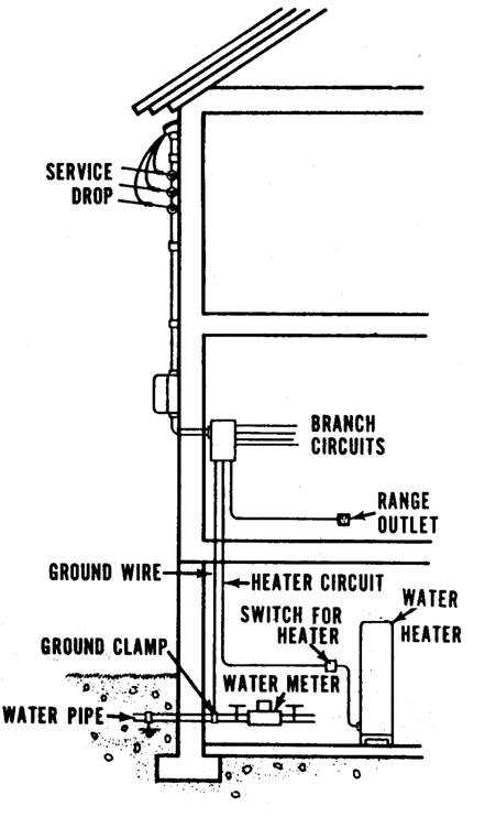
Figure 11.7. Typical Service Entrance
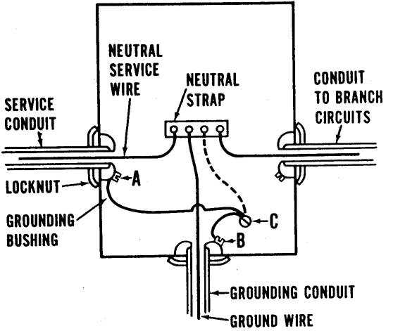
Figure 11.8. Grounding Scheme
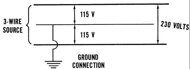
Figure 11.9. Grounding
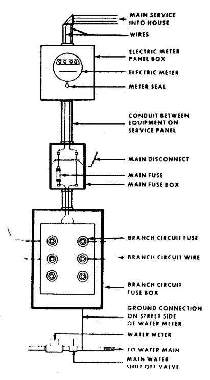
Figure 11.10. Three-wire Service
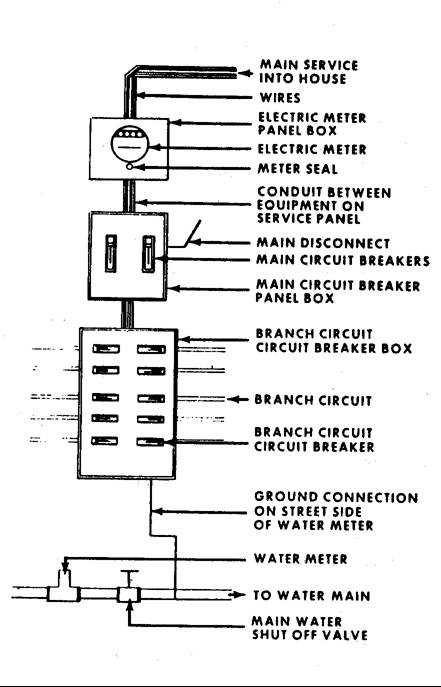
Figure 11.11. Two-wire Service
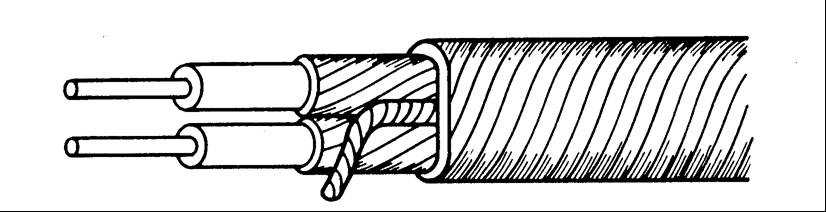
Figure 11.12. Wire Markings
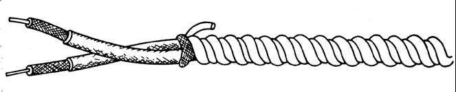
Figure 11.13. Armored Cable
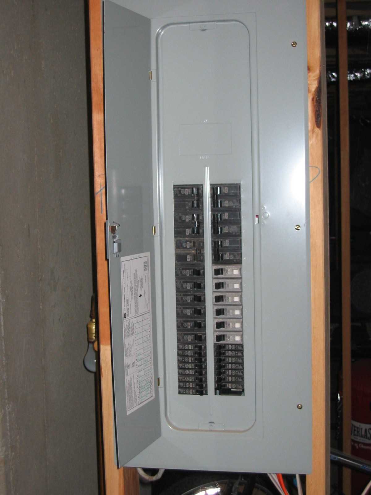
Figure 11.14. 200-Amp Service Box
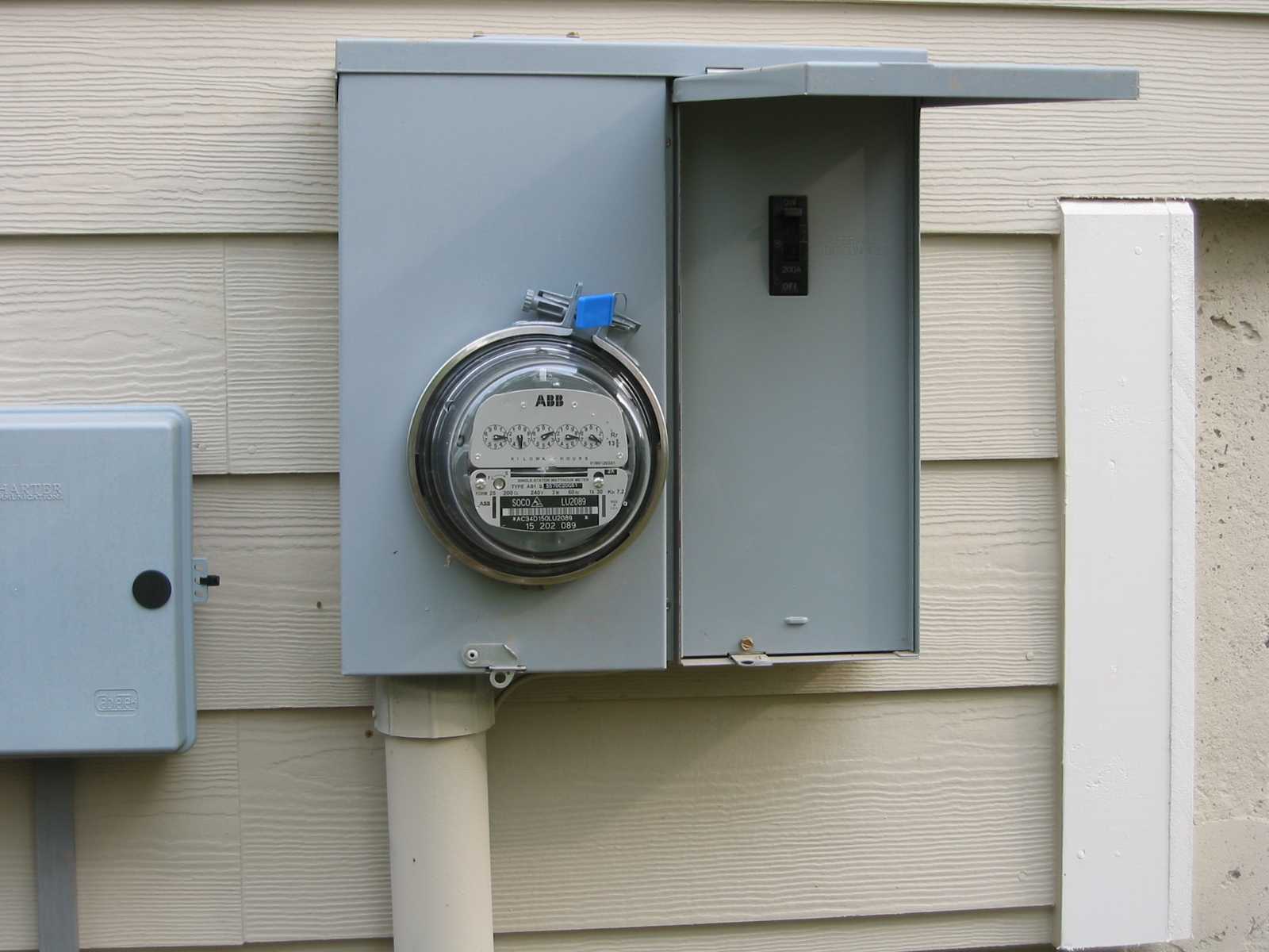
Figure 11.15. External Power Shutoff and Meter
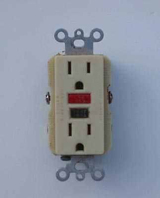
Figure 11.16. Ground Fault Circuit Interruptor

Figure 11.17. Arc Interrupter
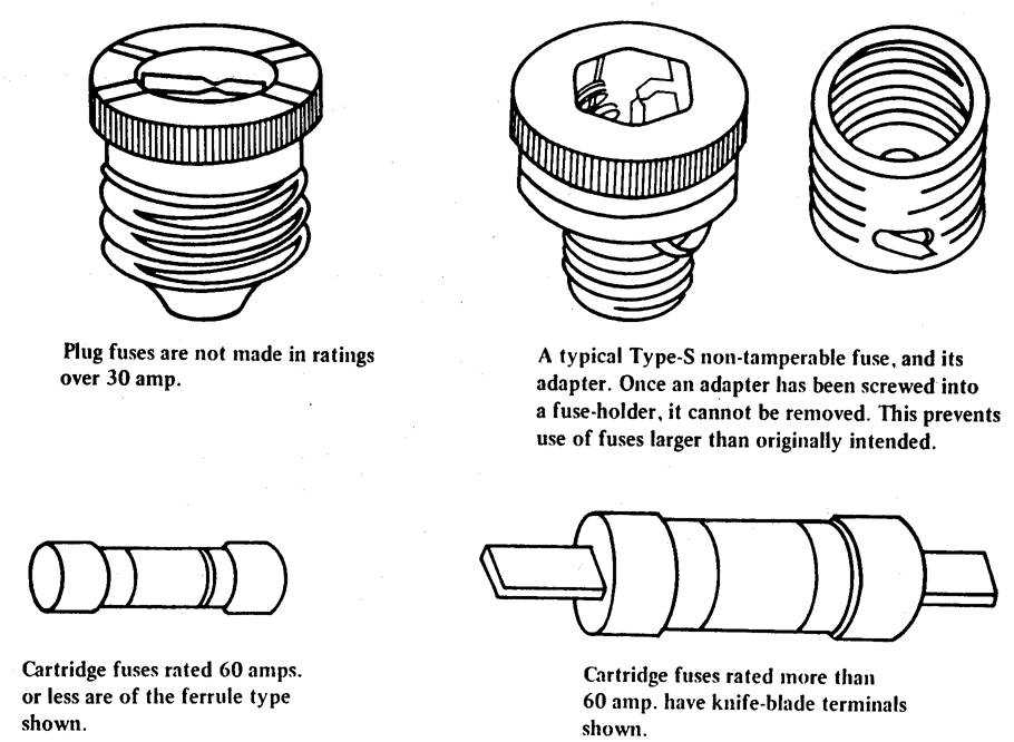
Figure 11.18. Types of Fuses
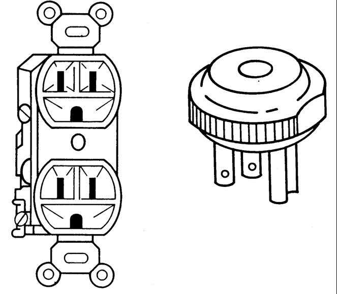
Figure 11.19. Appliance Ground and Grounded Plug
- Page last reviewed: October 1, 2009
- Page last updated: December 8, 2009
- Content source: