

Chapter 10 Figures
 ShareCompartir
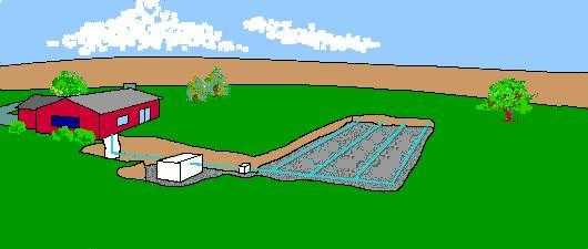
Figure 10.1. Conventional On-site Septic System
Effluent leaves home through a pipe, enters a septic tank, travels through a distribution
box to a trench absorption system composed of perforated pipe.
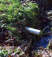
Figure 10.2. Straight Pipe Discharge
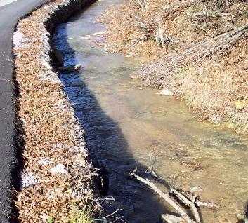
Figure 10.3. Clear Creek Water Contaminated With Sewage
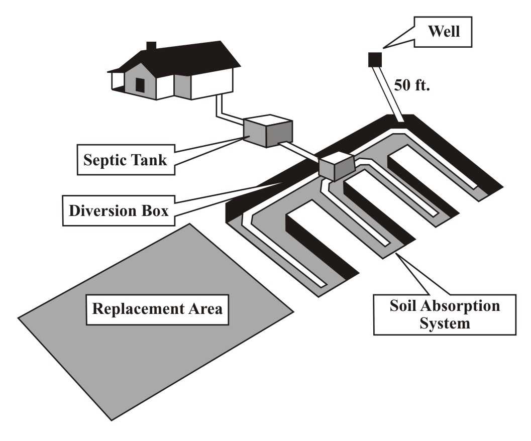
Figure 10.4. Septic Tank System
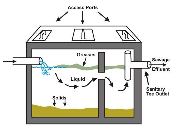
Figure 10.5. Septic Tank
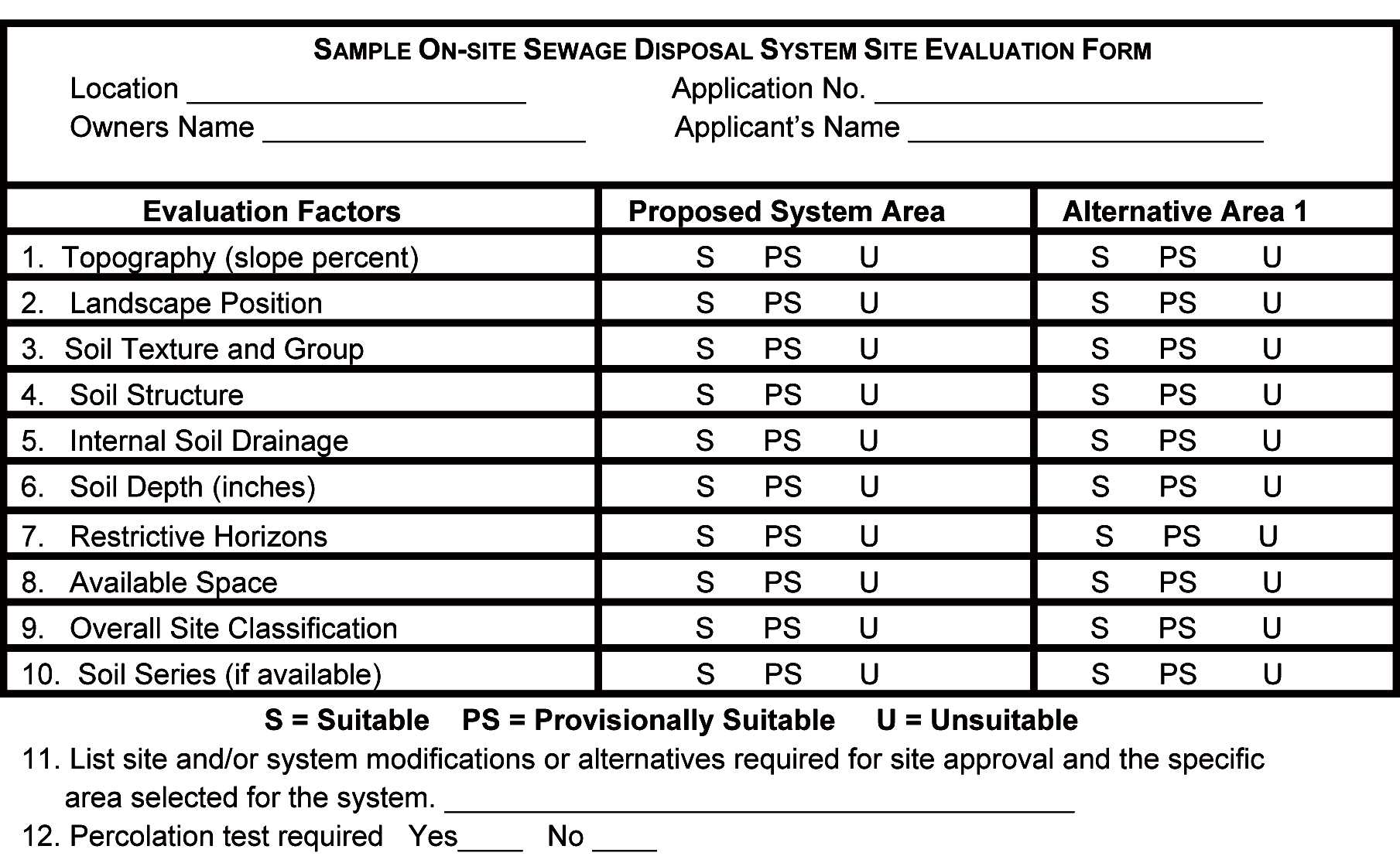
Figure 10.6. On-site Sewage Disposal System Site Evaluation Form
Figure 10.7. Cross-section of an Absorption Field
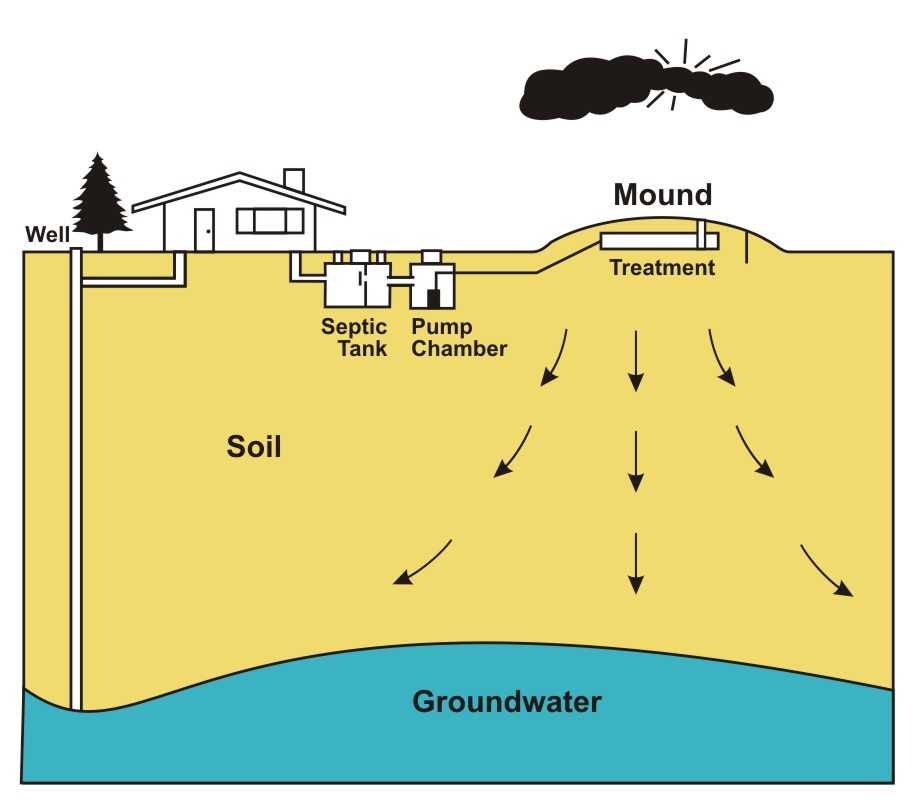
Figure 10.8. Mound System Cutaway
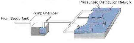
Figure 10.9. Low Pressure On-site System
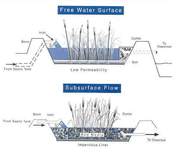
Figure 10.10. Plant-rock Filter System
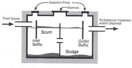
Figure 10.11. Sludge and Scum in Multicompartment Septic Tank
- Page last reviewed: October 1, 2009
- Page last updated: December 8, 2009
- Content source: