


Application of the ILO International Classification of Radiographs of Pneumoconioses to Digital Chest Radiographic Images
 ShareCompartir
July 2008
DHHS (NIOSH) Publication Number 2008-139
Go back to Workshop Index page.
A NIOSH Scientific Workshop
DISCLAIMER: The findings and conclusions in these proceedings are those of the authors and do not necessarily represent the official position of the National Institute for Occupational Safety and Health (NIOSH). Mention of any company or product does not constitute endorsement by NIOSH. In addition, citations to Web sites external to NIOSH do not constitute NIOSH endorsement of the sponsoring organizations or their programs or products. Furthermore, NIOSH is not responsible for the content of these Web sites.
Acquisition of digital chest images for pneumoconiosis classification: Methods, procedures, and hardware
Ehsan Samei, PhD
Duke Advanced Imaging Laboratories (DAI Labs)
Department of Radiology
Duke University Medical Center, Durham, NC 27705
Phone: 919-684-1440
Fax: 919-684-1491
Email: samei@duke.edu
Introduction
Digital radiography is rapidly replacing analog screen-film radiography in most applications including chest radiography (1). This conversion is fueled by the general trend within the medical community to “go digital,” and the many operational advantages that digital systems can provide when compared to conventional screen-film systems. Those include the ability to manipulate the image post-acquisition, thus giving the physician full flexibility to visualize the features of interest within the image. Furthermore, most digital radiographic sensors offer a markedly wider dynamic range than that of screen-film systems. As such, digital systems can better “tolerate” some level of under- or over-exposure and still provide a clinically-acceptable image; such instances in analog operation leads to overly bright or dark film images of suboptimal quality. Furthermore, digital radiography conveniently provides the image information in digital format, enabling quantification and computer analysis of image features. Finally, a digital image enables electronic archival and distribution, which in turn provide certain economic advantages and enable concurrent access to images across the clinical enterprise. These attributes of digital radiography provide notable advantages of the technology for classification of pneumoconiosis as they enable accessible, standardized image data for visual interpretation or automated classification.
While the advantages noted above are valid and true, they are more reflective of the inherent potentials of digital radiography as opposed to its practical reality. Those advantages may only be realized with careful planning, proper implementation, and attention to operational issues unique to the technology. As an example, the flexibility of being able to manipulate the appearance of a digital image post-acquisition is rarely exploited. The actual software tools for post-processing an image are generallyprovided, not at the display workstation used by the physician, but rather at the imaging system console operated by the radiologic technologists. Most images are processed automatically with no intervention even by the technologist. The physician is only provided with the most rudimentary form of image manipulation, window/leveling and zooming. And even with those, the workload and time constraints of clinical practice prevent most physicians from taking full advantage of those functionalities.
The theoretical advantages of digital radiography can in fact become inconsequential or even disadvantages. First of all, if the flexibility of image appearance is not effectively used to provide superior visualization, that advantage is not realized. But more importantly, that flexibility creates a potential for images to be processed in a sub-optimal fashion: In most clinical settings, raw digital images undergo an automated post-processing governed by the post-processing techniques and parameters set by the vendor. There have been only rare studies on the impact of those parameters on diagnostic performance. An image can be presented in multiple different ways by different systems, even by those from the same manufacturer. In this non-standardized and variable form, the images, as presented, are interpreted by physicians. Therefore, unless image quality parameters are optimized and standardized, the flexibility of digital radiography systems can lead to inconsistent image appearance, inconsistent clinical decision-making, and possible misdiagnosis.
Similar examples may also be given for the other two noted advantages of digital radiography. The “tolerance” of digital systems enables technologists to capture higher quality images at increased dose to the patient. That tendency has led to a documented “exposure creep” in digital operations in multiple clinical operations, thus leading to patient over-exposure (2). Similarly, an improper set-up of the Picture Archiving and Communication Systems (PACS) that enable electronic distribution and archiving of digital images has led to lost studies, inefficient workflows, and increased cost of operation due to uncontrolled printing and rapid turnover of computational equipment.
These examples highlight the fact that the potential advantages of digital radiography should not be considered automatic, or taken for granted. Implementers and users need to pay careful attention to the nuances associated with the features and practical use of digital radiographic systems, and to the way they are incorporated into the workflow of a clinical operation.
Common Aspects of Digital Radiography Systems
Digital radiography is accomplished using a host of differing technologies (Table 1, Figure 1), which are summarized in the subsequent sections. But while digital radiography systems differ from each other substantially, in terms of instrumentation and implementation, they all share certain common characteristics. Some of those characteristics are listed below:
- Digital radiography systems are implemented similarly to screen-film systems in the way the image sensor is geometrically positioned with respect to the x-ray source and the patient. The only difference is that the sensor is now digital as opposed to analog.
- X-ray scatter continues to be a prominent and undesirable component of x-ray imaging affecting the quality of digital images, as in analog images. Thus, the techniques traditionally used to reduce scatter in screen-film images, e.g., use of anti-scatter grid and air gap, will be similarly applicable to digital systems.
- In nearly all digital radiography systems, initially the x-ray energy is captured by an analog (ie, continuous) medium. The capture medium converts the x-ray energy promptly or in a delayed fashion into either charge or visible light, which is then collected and digitized to form the digital image.
- In all digital systems, the raw image data must be processed to make them suitable for viewing by a physician. Initially, images are corrected for a priori non-uniformity of response from the image detector. The useful, anatomically-relevant range of signals from the sensor is then identified. Common techniques include collimation identification and histogram analysis. The data are then appropriately post-processed (ie, gray-scaled and contrast-enhanced) to provide an acceptable image appearance.
Table 1. Current technologies for digital chest radiography
| Technology | Capture element | Coupling | Sensor | Typical pixel size |
|---|---|---|---|---|
| CR | Barium halide | PSL light-guide | PSL signal digitization | 0.1-0.2 mm |
| CCD or CMOS-based | Gd2O2S or CsI | Lens or fiber-optic taper | CCD or CMOS | 0.06-0.2 mm |
| Indirect flat-panel | Gd2O2S or CsI | Contact layer | TFT array | 0.14-0.2 mm |
| Direct flat-panel | a-Se | None | TFT array | 0.12-0.15 mm |
| Fan-beam | CsI | Fiber-optic taper | CCD | 0.162 mm |
| Film digitization | Gd2O2S/film | digitizer | Variable | Variable |
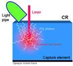
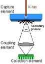
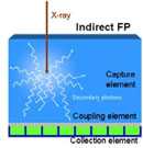
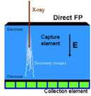
Figure 1. Conceptual schematic of detector components in CR (a), CCD-based (b), indirect flat-panel (c) and direct flat-panel (d) systems (Used by permission from 4. Samei E. Performance of Digital Radiography Detectors: Factors Affecting Sharpness and Noise. In: Advances in Digital Radiography, E Samei (ed). Radiological Society of North America (RSNA) Publication, Categorical Course Syllabus, Oak Brook, IL, 2003, pp. 49-61).
Computed Radiography (CR)
First commercially introduced in 1983, Computed radiography (CR) is the most commonly used digital radiography modality today. There are currently more than 10,000 systems in clinical use worldwide. CR technology is based on certain halide-based phosphor materials having an energy storage and excitation property, known as photostimulable luminance (PSL), which enables them to store x-ray energy temporarily and release that energy upon excitation by a laser beam at a later time (3). Some common phosphor materials include BaFBr: Eu, and BaF(BrI):Eu. The phosphor particulates are bonded with a cohesive material forming a turbid structure, and deposited on a base for mechanical support.
The phosphor screen is positioned within a cassette not unlike screen-film cassettes. Once exposed to x-ray, a fraction of the x-ray energy is stored by the phosphor screen. After exposure, the cassette is processed by a scanning system which extracts the screen from the cassette, moves it across a scanning laser beam, collects the resulting light signal released by the screen, and digitizes and processes the signals to form the image (Figure 2). The screen is then exposed to a flood of uniform light to erase any residual signals that might have remained on the screen. The erased screen is reinserted back into the cassette for its next use.
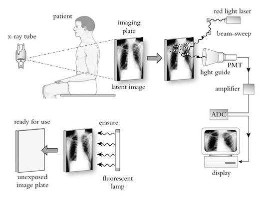
Figure 2. Image formation in CR (used by permission from Zhao W, Andriole K, Samei E. Digital Radiography and Fluoroscopy. In: Advances in Medical Physics 2006, AB Wolbarst, RG Zamenhof, and WR Hendee (eds). Medical Physics Publishing, Madison, WI, 2006, pp. 1-23).
One of clinical advantages of CR is its cassette-based operation. It enables easy retrofitting of existing film-based x-ray equipment and convenient positioning of patients, especially in portable settings. Furthermore, a single scanning system can serve multiple examination rooms, thus providing an added economic advantage. However, CR has historically offered lower image quality than flat-panel-based digital radiography systems. This is primarily due to spreading of the laser beam within the bulk of the turbid phosphor material during the scanning process. The dispersion of the laser energy causes a fundamental loss of image resolution. To keep that loss at clinically acceptable levels, the screen thickness cannot exceed certain limits, thus imposing a cap on the maximum detection efficiency that CR systems can provide.
The common metric by which the image quality of digital radiographic systems is measured is the detective quantum efficiency (DQE). The DQE is a measure of maximum SNR that an image system can provide in response to unit incident exposure. An ideal radiographic system will have a DQE of 100%, implying fully efficient use of incident exposure and the patient dose involved in the image formation. The DQE of CR systems at x-ray energies used for chest radiography is within the 15-25% range.
In recent years, there have been multiple developments in improving the DQE of CR systems. Those include better control of the distribution of the sizes of phosphor particulates in the screen, the use of structured CsBr phosphor to enable thicker phosphor screens without concern about the loss of resolution as in turbid phosphor screens, and the collection of the PSL light from both sides of the phosphor screen (4). These developments have generally led to a more favorable standing of CR among digital radiographic systems in terms of image quality and dose efficiency.
CCD/CMOS-based Systems
The advent of low-cost Charged Couple Device (CCD) and Complementary metal–oxide–semiconductor (CMOS) electronics has enabled their wide-spread use in the digital photography market. Naturally, the earliest developments in digital radiography have tried to take advantage of this technology. The digital radiography systems based on CCD or CMOS generally employ a phosphor screen (either turbid, made of rare-earth scintillators, or needle-structured, such as cesium iodide - CsI). The screen is optically coupled to the CCD/CMOS sensor via a camera lens system or a fiber-optic coupler (Figure 1b) (1). Upon x-ray exposure, the light generated at the screen is thus captured by the CCD/CMOS sensor and recorded as a digital image, which is then further processed for display.
CCD/CMOS-based systems tend to be less costly than competitive technologies, considering the high volume (and thus lower cost) of CCD/CMOS sensors for the consumer market. However, they have generally lower performance when compared to flat-panel systems. This is primarily due to a poor light collection efficiency; the majority of light photons generated by x-rays at the screen are not collected by the CCD/CMOS sensor due to the fact that the sensor is generally smaller than the screen and the camera system is unable to capture an adequate fraction of light photons released from the phosphor screen. This loss of information is coined “secondary quantum sink” in the scientific literature (5). Newer systems have tried to remedy this issue to some extent, but the performance of these systems still falls short of that of flat-panel systems. The DQE of current CCD/CMOS systems at x-ray energies used for chest radiography is within 15-20% range.
Indirect Flat-Panel Systems
The inefficiency of light collection in CCD-based systems was a motivation to replace the light sensor with a sensor large enough to be directly coupled with the phosphor screen. In doing so, the light collection efficiency can be dramatically enhanced leading to improved image quality. The advent of digital flat-panel displays provided the technological foundation to enable that goal.
Indirect flat-panel detectors use a phosphor screen similar to that used in CCD/CMOS-based systems. Structured thallium-doped CsI is commonly used. The screen is directly coupled to a flat-panel sensor. The sensor is made of a thin-film transistor (TFT)/photodiode amorphous silicone array deposited on a sheet of glass (Figure 3) (6). Each transistor serves as a separate light sensor collecting the light photons and converting them to charge. The charge deposited in pixel circuits is read line by line through the gate and data lines. The data are then corrected for panel non-uniformities and bad pixels and processed for display.
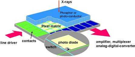
Figure 3. Schematic of a flat-panel detector.
As a phosphor-based imaging system, indirect flat-panel detectors have resolution properties similar to other phosphor-based systems (eg, CR, CCD/CMOS-based systems). Thicker phosphor layers enable better x-ray detection efficiency at the expense of lower resolution. The use of structured phosphor, such as CsI, however, provides a more favorable balance between resolution and detection efficiency, enabling improved DQE at comparable resolution to turbid-phosphor-based systems (Figure 4). The DQE of current systems at x-ray energies used for chest radiography is within 45-55% range for indirect detectors with CsI and about half of that for those with turbid phosphor.
Advancement in the development of indirect flat panel systems of improved quality have focused on the use of phosphors of higher efficiency and light yield, reducing the inherent fill factors of the pixels defining the useful real estate of the pixel area, an improved noise performance of the TFT array.
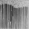
Figure 4. Structured (a) and turbid (b) phosphor.
Direct Flat-panel Systems
Direct flat-panel systems deploy a technology very similar to that of their indirect counterparts (Figure 1d, Figure 3). A direct flat-panel detector uses a TFT matrix array very similar to that used for the other detector type, thus the common “flat-panel” designation. However, the capture medium, instead of a phosphor, is a photo-conductor. Current detectors typically employ amorphous selenium for that purpose. The x-ray photons can be captured by the photo conductor layer and their energy is directly converted to charge with no intermediary light conversion stage. With a high voltage electric field applied across the capture layer, the generated charge is directed towards electrodes and eventually deposited in the capacitors associated with the pixels. The pixel charge is then read line by line through the gate and data lines. The data are then corrected for panel non-uniformities and bad pixels and processed for display.
An advantage of direct flat-panel detectors is that the collected charges do not disperse laterally in the bulk of the capture medium. This is in stark contrast to phosphor-based detectors for which the lateral dispersion of light limits their resolution and thus in turn their detection efficiency. Consequently, direct detectors offer near perfect sharpness. However, the “cost” of this sharpness is the artifactual enhancement of radiographic noise that is no longer blurred by the limited resolution of the detector. This enhancement, known as noise aliasing, limits the DQE of direct systems (6). Current direct flat-panel systems offer high resolution and DQE in the 20-30% range for x-ray energies applicable to chest radiography.
Fan-beam Radiography Systems
As noted earlier, scattered radiation is an ever-present source of image quality degradation in x-ray imaging. The common solutions to reducing that influence involve the use of anti-scatter grid and air gap. However, the former leads to increased patient dose due to attenuation of the primary beam, and the latter necessitates the use of smaller focal spots and larger detectors to provide adequate coverage of the anatomy of interest. An alternative approach involves the use of a fan beam (as opposed to a cone beam) to acquire the image. This approach does not have the disadvantages associated with alternative techniques.
Fan-beam imaging can be undertaken with any type of imaging sensor listed above with certain hardware and software modifications. The current commercial offering uses a CsI-capture element optically coupled to a CCD sensor to capture the image from a moving fan beam (Figure 5) (7). The modulation transfer function and resolution are comparable to other phosphor-based systems, and system DQE ranges from 15-20% range for chest x-ray beams. However, the imaging geometry cuts the scatter fraction by 2-3 times compared to alternative cone-beam geometry, leading to a significant enhancement of eDQE and the image quality per unit incident exposure (7).
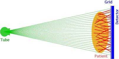
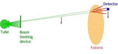
Figure 5. Cone-beam radiography (a) versus fan-beam radiography (b).
Digital Radiography via Digitization
The imaging systems noted above all utilize an electronic sensor to capture the image. However, it is also possible to obtain a digital image by digitizing the analog screen film. That can provide a digital representation of the analog image, which can be used for electronic archival, transmission, and display.
While this approach for digital radiography has merits in enabling integration of prior analog images or those from other facilities with an existing digital operation, it has certain important shortcomings. These include loss of image quality in the digitization process, inconsistent image appearance from film to film due to variations in exposure levels or film/screen type, and sub-optimal display of the images which are optimally gray-scaled for viewing on a view-box as opposed to an electronic display. Because of these reasons, this mode of digital radiography is considered sub-optimal and supplemental at best.
Conclusions and Recommendations
Digital radiography offers distinct advantages in comparison to analog screen-film radiography. Current commercial offerings represent a host of differing technologies with different image quality attributes. As such, the current initiative needs address the similarities and differences among the diverse available systems. These similarities and differences must be taken into consideration when comparing images that might be generated by different technologies. Furthermore, considering the diversity of technologies and implementations as well as the added complexity of operational variability, it is equally important to ensure that the systems are utilized under controlled unifying conditions. Those should include the use of standardized image acquisition and processing protocols, and robust quality control and preventative maintenance programs. Proper operation should be further ensured through an accreditation program.
References
- Yaffe MJ, Rowlands JA. X-ray detectors for digital radiography. Phys Med Biol 1997; 42:1-39.
- Seibert JA. Computed radiography: Technology and quality assurance. In: The Expanding Role of Medical Physics in Diagnostic Imaging. Ed. Frey GD, Sprawls P. Madison, WI; Medical Physics Publishing, pp. 38-84 (1997).
- Sonoda M, Takano M, Miyahara J, Kato H. Computed radiography utilizing scanning laser stimulated luminescence. Radiology, 148:833-838 (1983).
- Samei E. Performance of Digital Radiography Detectors: Factors Affecting Sharpness and Noise. In: Advances in Digital Radiography, E Samei (ed). Radiological Society of North America (RSNA) Publication, Categorical Course Syllabus, Oak Brook, IL, 2003, pp. 49-61.
- Cunningham IA, Westmore MS, Fenster A.A spatial-frequency dependent quantum accounting diagram and detective quantum efficiency model of signal and noise propagation in cascaded imaging systems. Medical Physics, 1994; 21:417-427.
- Samei E, Flynn MJ. An experimental comparison of detector performance for direct and indirect digital radiography systems. Med Phys 2003; 30:608-622.
- Samei E, Lo JY, Yoshizumi TT, Dobbins III JT, Jesneck JL, Floyd Jr CE, McAdams HP, Ravin CE. Comparative scatter and dose performance of slot-scan and full-field digital chest radiographic systems. Radiology, 2005; 235:940-949.
- Page last reviewed: June 6, 2014
- Page last updated: June 6, 2014
- Content source:
- National Institute for Occupational Safety and Health Education and Information Division