Patch clamp
The patch clamp technique is a laboratory technique in electrophysiology used to study ionic currents in individual isolated living cells, tissue sections, or patches of cell membrane. The technique is especially useful in the study of excitable cells such as neurons, cardiomyocytes, muscle fibers, and pancreatic beta cells, and can also be applied to the study of bacterial ion channels in specially prepared giant spheroplasts.
Patch clamping can be performed using the voltage clamp technique. In this case, the voltage across the cell membrane is controlled by the experimenter and the resulting currents are recorded. Alternatively, the current clamp technique can be used. In this case the current passing across the membrane is controlled by the experimenter and the resulting changes in voltage are recorded, generally in the form of action potentials.
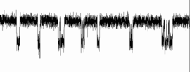
Erwin Neher and Bert Sakmann developed the patch clamp in the late 1970s and early 1980s. This discovery made it possible to record the currents of single ion channel molecules for the first time, which improved understanding of the involvement of channels in fundamental cell processes such as action potentials and nerve activity. Neher and Sakmann received the Nobel Prize in Physiology or Medicine in 1991 for this work.[1]
Basic technique
Set-up
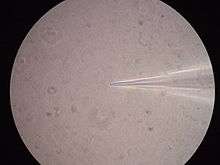
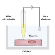
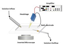
During a patch clamp recording, a hollow glass tube known as a micropipette or patch pipette filled with an electrolyte solution and a recording electrode connected to an amplifier is brought into contact with the membrane of an isolated cell. Another electrode is placed in a bath surrounding the cell or tissue as a reference ground electrode. An electrical circuit can be formed between the recording and reference electrode with the cell of interest in between.
The solution filling the patch pipette might match the ionic composition of the bath solution, as in the case of cell-attached recording, or match the cytoplasm, for whole-cell recording. The solution in the bath solution may match the physiological extracellular solution, the cytoplasm, or be entirely non-physiological, depending on the experiment to be performed. The researcher can also change the content of the bath solution (or less commonly the pipette solution) by adding ions or drugs to study the ion channels under different conditions.
Depending on what the researcher is trying to measure, the diameter of the pipette tip used may vary, but it is usually in the micrometer range.[2] This small size is used to enclose a membrane surface area or "patch" that often contains just one or a few ion channel molecules.[3] This type of electrode is distinct from the "sharp microelectrode" used to puncture cells in traditional intracellular recordings, in that it is sealed onto the surface of the cell membrane, rather than inserted through it.
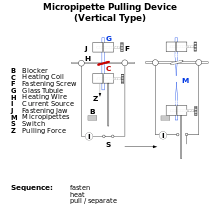
In some experiments, the micropipette tip is heated in a microforge to produce a smooth surface that assists in forming a high resistance seal with the cell membrane. To obtain this high resistance seal, the micropipette is pressed against a cell membrane and suction is applied. A portion of the cell membrane is suctioned into the pipette, creating an omega-shaped area of membrane which, if formed properly, creates a resistance in the 10–100 gigaohms range, called a "gigaohm seal" or "gigaseal".[3] The high resistance of this seal makes it possible to isolate electronically the currents measured across the membrane patch with little competing noise, as well as providing some mechanical stability to the recording.[4]
Recording
Many patch clamp amplifiers do not use true voltage clamp circuitry, but instead are differential amplifiers that use the bath electrode to set the zero current (ground) level. This allows a researcher to keep the voltage constant while observing changes in current. To make these recordings, the patch pipette is compared to the ground electrode. Current is then injected into the system to maintain a constant, set voltage. However much current is needed to clamp the voltage is opposite in sign and equal in magnitude to the current through the membrane.[3]
Alternatively, the cell can be current clamped in whole-cell mode, keeping current constant while observing changes in membrane voltage.[5]
Variations
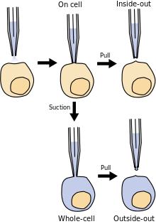
Several variations of the basic technique can be applied, depending on what the researcher wants to study. The inside-out and outside-out techniques are called "excised patch" techniques, because the patch is excised (removed) from the main body of the cell. Cell-attached and both excised patch techniques are used to study the behavior of individual ion channels in the section of membrane attached to the electrode.
Whole-cell patch and perforated patch allow the researcher to study the electrical behavior of the entire cell, instead of single channel currents. The whole-cell patch, which enables low-resistance electrical access to the inside of a cell, has now largely replaced high-resistance microelectrode recording techniques to record currents across the entire cell membrane.
Cell-attached patch
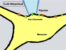
For this method, the pipette is sealed onto the cell membrane to obtain a gigaseal, while ensuring that the cell membrane remains intact. This allows the recording of currents through single, or a few, ion channels contained in the patch of membrane captured by the pipette. By only attaching to the exterior of the cell membrane, there is very little disturbance of the cell structure.[3] Also, by not disrupting the interior of the cell, any intracellular mechanisms normally influencing the channel will still be able to function as they would physiologically.[6] Using this method it is also relatively easy to obtain the right configuration, and once obtained it is fairly stable.[7]
For ligand-gated ion channels or channels that are modulated by metabotropic receptors, the neurotransmitter or drug being studied is usually included in the pipette solution, where it can interact with what used to be the external surface of the membrane. The resulting channel activity can be attributed to the drug being used, although it is usually not possible to then change the drug concentration inside the pipette. The technique is thus limited to one point in a dose response curve per patch. Therefore, the dose response is accomplished using several cells and patches. However, voltage-gated ion channels can be clamped successively at different membrane potentials in a single patch. This results in channel activation as a function of voltage, and a complete I-V (current-voltage) curve can be established in only one patch. Another potential drawback of this technique is that, just as the intracellular pathways of the cell are not disturbed, they cannot be directly modified either.[7]
Inside-out patch
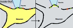
In the inside-out method, a patch of the membrane is attached to the patch pipette, detached from the rest of the cell, and the cytosolic surface of the membrane is exposed to the external media, or bath.[8] One advantage of this method is that the experimenter has access to the intracellular surface of the membrane via the bath and can change the chemical composition of what the surface of the membrane is exposed to. This is useful when an experimenter wishes to manipulate the environment at the intracellular surface of single ion channels. For example, channels that are activated by intracellular ligands can then be studied through a range of ligand concentrations.
To achieve the inside-out configuration, the pipette is attached to the cell membrane as in the cell-attached mode, forming a gigaseal, and is then retracted to break off a patch of membrane from the rest of the cell. Pulling off a membrane patch often results initially in the formation of a vesicle of membrane in the pipette tip, because the ends of the patch membrane fuse together quickly after excision. The outer face of the vesicle must then be broken open to enter into inside-out mode; this may be done by briefly taking the membrane through the bath solution/air interface, by exposure to a low Ca2+ solution, or by momentarily making contact with a droplet of paraffin or a piece of cured silicone polymer.[9]
Whole-cell recording or whole-cell patch
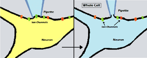
Whole-cell recordings involve recording currents through multiple channels simultaneously, over the membrane of the entire cell. The electrode is left in place on the cell, as in cell-attached recordings, but more suction is applied to rupture the membrane patch, thus providing access from the interior of the pipette to the intracellular space of the cell. This provides a means to administer and study how treatments (ex. drugs) can affect cells in real time.[10] Once the pipette is attached to the cell membrane, there are two methods of breaking the patch. The first is by applying more suction. The amount and duration of this suction depends on the type of cell and size of the pipette. The other method requires a large current pulse to be sent through the pipette. How much current is applied and the duration of the pulse also depend on the type of cell.[7] For some types of cells, it is convenient to apply both methods simultaneously to break the patch.
The advantage of whole-cell patch clamp recording over sharp electrode technique recording is that the larger opening at the tip of the patch clamp electrode provides lower resistance and thus better electrical access to the inside of the cell.[11][10] A disadvantage of this technique is that because the volume of the electrode is larger than the volume of the cell, the soluble contents of the cell's interior will slowly be replaced by the contents of the electrode. This is referred to as the electrode "dialyzing" the cell's contents.[7] After a while, any properties of the cell that depend on soluble intracellular contents will be altered. The pipette solution used usually approximates the high-potassium environment of the interior of the cell to minimize any changes this may cause. There is often a period at the beginning of a whole-cell recording when one can take measurements before the cell has been dialyzed.[7]
Outside-out patch
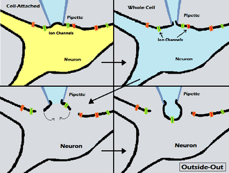
The name "outside-out" emphasizes both this technique's complementarity to the inside-out technique, and the fact that it places the external rather than intracellular surface of the cell membrane on the outside of the patch of membrane, in relation to the patch electrode.[6]
The formation of an outside-out patch begins with a whole-cell recording configuration. After the whole-cell configuration is formed, the electrode is slowly withdrawn from the cell, allowing a bulb of membrane to bleb out from the cell. When the electrode is pulled far enough away, this bleb will detach from the cell and reform as a convex membrane on the end of the electrode (like a ball open at the electrode tip), with the original outside of the membrane facing outward from the electrode.[6] As the image at the right shows, this means that the fluid inside the pipette will be simulating the intracellular fluid, while a researcher is free to move the pipette and the bleb with its channels to another bath of solution. While multiple channels can exist in a bleb of membrane, single channel recordings are also possible in this conformation if the bleb of detached membrane is small and only contains one channel.[12]
Outside-out patching gives the experimenter the opportunity to examine the properties of an ion channel when it is isolated from the cell and exposed successively to different solutions on the extracellular surface of the membrane. The experimenter can perfuse the same patch with a variety of solutions in a relatively short amount of time, and if the channel is activated by a neurotransmitter or drug from the extracellular face, a dose-response curve can then be obtained.[13] This ability to measure current through exactly the same piece of membrane in different solutions is the distinct advantage of the outside-out patch relative to the cell-attached method. On the other hand, it is more difficult to accomplish. The longer formation process involves more steps that could fail and results in a lower frequency of usable patches.
Perforated patch
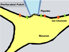
This variation of the patch clamp method is very similar to the whole-cell configuration. The main difference lies in the fact that when the experimenter forms the gigaohm seal, suction is not used to rupture the patch membrane. Instead, the electrode solution contains small amounts of an antifungal or antibiotic agent, such as amphothericin-B, nystatin, or gramicidin, which diffuses into the membrane patch and forms small pores in the membrane, providing electrical access to the cell interior.[14] When comparing the whole-cell and perforated patch methods, one can think of the whole-cell patch as an open door, in which there is complete exchange between molecules in the pipette solution and the cytoplasm. The perforated patch can be likened to a screen door that only allows the exchange of certain molecules from the pipette solution to the cytoplasm of the cell.
Advantages of the perforated patch method, relative to whole-cell recordings, include the properties of the antibiotic pores, that allow equilibration only of small monovalent ions between the patch pipette and the cytosol, but not of larger molecules that cannot permeate through the pores. This property maintains endogenous levels of divalent ions such as Ca2+ and signaling molecules such as cAMP. Consequently, one can have recordings of the entire cell, as in whole-cell patch clamping, while retaining most intracellular signaling mechanisms, as in cell-attached recordings. As a result, there is reduced current rundown, and stable perforated patch recordings can last longer than one hour.[14] Disadvantages include a higher access resistance, relative to whole-cell, due to the partial membrane occupying the tip of the electrode. This may decrease current resolution and increase recording noise. It can also take a significant amount of time for the antibiotic to perforate the membrane (about 15 minutes for amphothericin-B, and even longer for gramicidin and nystatin). The membrane under the electrode tip is weakened by the perforations formed by the antibiotic and can rupture. If the patch ruptures, the recording is then in whole-cell mode, with antibiotic contaminating the inside of the cell.[14]
Loose patch
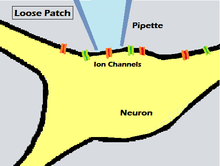
Loose patch clamp is different from the other techniques discussed here in that it employs a loose seal (low electrical resistance) rather than the tight gigaseal used in the conventional technique. This technique was used as early as the year 1961, as described in a paper by Strickholm on the impedance of a muscle cell's surface,[15] but received little attention until being brought up again and given a name by Almers, Stanfield, and Stühmer in 1982,[16] after patch clamp had been established as a major tool of electrophysiology.
To achieve a loose patch clamp on a cell membrane, the pipette is moved slowly towards the cell, until the electrical resistance of the contact between the cell and the pipette increases to a few times greater resistance than that of the electrode alone. The closer the pipette gets to the membrane, the greater the resistance of the pipette tip becomes, but if too close a seal is formed, and it could become difficult to remove the pipette without damaging the cell. For the loose patch technique, the pipette does not get close enough to the membrane to form a gigaseal or a permanent connection, nor to pierce the cell membrane.[17] The cell membrane stays intact, and the lack of a tight seal creates a small gap through which ions can pass outside the cell without entering the pipette.
A significant advantage of the loose seal is that the pipette that is used can be repeatedly removed from the membrane after recording, and the membrane will remain intact. This allows repeated measurements in a variety of locations on the same cell without destroying the integrity of the membrane. This flexibility has been especially useful to researchers for studying muscle cells as they contract under real physiological conditions, obtaining recordings quickly, and doing so without resorting to drastic measures to stop the muscle fibers from contracting.[16] A major disadvantage is that the resistance between the pipette and the membrane is greatly reduced, allowing current to leak through the seal, and significantly reducing the resolution of small currents. This leakage can be partially corrected for, however, which offers the opportunity to compare and contrast recordings made from different areas on the cell of interest. Given this, it has been estimated that the loose patch technique can resolve currents smaller than 1 mA/cm2.[17]
Automatic patch clamping
Automated patch clamp systems have recently been developed, in order to collect large amounts of data inexpensively in a shorter period of time. Such systems typically include a single-use microfluidic device, either an injection molded or a polydimethylsiloxane (PDMS) cast chip, to capture a cell or cells, and an integrated electrode.
In one form of such an automated system, a pressure differential is used to force the cells being studied to be drawn towards the pipette opening until they form a gigaseal. Then, by briefly exposing the pipette tip to the atmosphere, the portion of the membrane protruding from the pipette bursts, and the membrane is now in the inside-out conformation, at the tip of the pipette. In a completely automated system, the pipette and the membrane patch can then be rapidly moved through a series of different test solutions, allowing different test compounds to be applied to the intracellular side of the membrane during recording.[18]
See also
- Bioelectronics
- Cable theory
- Channelome
- Channelomics
- GHK flux equation
- Goldman equation
- Microelectrode array
- Planar patch clamp
- Slice preparation
References
- "The Nobel Prize in Physiology or Medicine 1991". nobelprize.org. Nobel Media AB. Retrieved November 8, 2014.
- Bannister, Niel (November 1, 2012). Langton, Phil (ed.). Essential Guide to Reading Biomedical Papers: Recognizing and Interpreting Best Practice. Wiley-Blackwell. doi:10.1002/9781118402184. ISBN 9781118402184.
- Sakmann, B.; Neher, E. (1984). "Patch clamp techniques for studying ionic channels in excitable membranes". Annual Review of Physiology. 46: 455–472. doi:10.1146/annurev.ph.46.030184.002323. PMID 6143532.
- Sigworth, Fredrick J.; Neher, E. (October 2, 1980). "Single Na+ channel currents observed in cultured rat muscle cells". Nature. 287 (5781): 447–449. Bibcode:1980Natur.287..447S. doi:10.1038/287447a0. PMID 6253802.
- Ellen Covey; Matt Carter (2015). Basic Electrophysiological Methods. Oxford University Press. pp. 22–. ISBN 978-0-19-993980-0.
- Hamill OP, Marty A, Neher E, Sakmann B, Sigworth FJ.; Marty; Neher; Sakmann; Sigworth (1981). "Improved patch-clamp techniques for high-resolution current recording from cells and cell-free membrane patches". Pflügers Archiv: European Journal of Physiology. 391 (2): 85–100. CiteSeerX 10.1.1.456.107. doi:10.1007/BF00656997. PMID 6270629.CS1 maint: multiple names: authors list (link)
- Molleman, Areles (March 6, 2003). Patch Clamping: An Introductory Guide To Patch Clamp Electrophysiology. Wiley. doi:10.1002/0470856521. ISBN 9780470856529.
- Veitinger, Sophie (2011-11-09). "The Patch-Clamp Technique". Science Lab. Leica Microsystems. Retrieved November 10, 2014.
- Ogden, David; Stanfield, Peter. "Patch Clamp Techniques" (PDF). utdallas.edu. pp. 53–78. Retrieved November 11, 2014.
- Segev, Amir; Garcia-Oscos, Francisco; Kourrich, Saïd (2016-06-15). "Whole-cell Patch-clamp Recordings in Brain Slices". Journal of Visualized Experiments (112): e54024. doi:10.3791/54024. ISSN 1940-087X. PMC 4927800. PMID 27341060.
- Staley, K.J.; Otis, T. S.; Mody, I (May 1, 1992). "Membrane properties of dentate gyrus granule cells: comparison of sharp microelectrode and whole-cell recordings". Journal of Neurophysiology. 67 (5): 1346–1358. doi:10.1152/jn.1992.67.5.1346. PMID 1597717.
- Howe, JR; Cull-Candy, SG; Colquhoun, D (Jan 1991). "Currents through single glutamate receptor channels in outside-out patches from rat cerebellar granule cells". Journal of Physiology. 432 (1): 143–202. doi:10.1113/jphysiol.1991.sp018381. PMC 1181322. PMID 1715916.
- von Beckerath, N; Adelsberger, H; Parzefall, F; Franke, C; Dudel, J (Apr 1995). "GABAergic inhibition of crayfish deep extensor abdominal muscle exhibits a steep dose-response relationship and a high degree of cooperativity". European Journal of Physiology. 429 (6): 781–788. doi:10.1007/bf00374801. PMID 7541524.
- Linley, John (2013). "11". In Gamper, Nikita (ed.). Perforated Whole-Cell Patch-Clamp Recording (Second ed.). Humana Press. pp. 149–157. ISBN 978-1-62703-351-0.
- Strickholm, A (1 Jul 1961). "Impedance of a Small Electrically Isolated Area of the Muscle Cell Surface". Journal of General Physiology. 44 (6): 1073–88. doi:10.1085/jgp.44.6.1073. PMC 2195146. PMID 19873540.
- Almers W, Stanfield PR, Stühmer W (1983). "Lateral distribution of sodium and potassium channels in frog skeletal muscle: measurements with a patch clamp method". Journal of Physiology. 336 (10): 261–284. doi:10.1113/jphysiol.1983.sp014580. PMC 1198969. PMID 6308223.
- Lupa, MT; Caldwell, JH (Nov 1991). "Effect of Agrin on the Distribution of Acetylcholine Receptors and Sodium Channels on Adult Skeletal Muscle Fibers in Culture". Journal of Cell Biology. 115 (3): 765–778. doi:10.1083/jcb.115.3.765. PMC 2289169. PMID 1655812.
- Bowlby, Mark; Merrill, Thomas; Vasilyev, Dmitry (2005). "Development of a Novel Automated Ion Channel Recording Method Using Inside-Out Whole-Cell Membranes". Journal of Biomolecular Screening. 10 (8): 806–813. doi:10.1177/1087057105279481. PMID 16234349.