Linear particle accelerator
A linear particle accelerator (often shortened to linac) is a type of particle accelerator that accelerates charged subatomic particles or ions to a high speed by subjecting them to a series of oscillating electric potentials along a linear beamline. The principles for such machines were proposed by Gustav Ising in 1924,[1] while the first machine that worked was constructed by Rolf Widerøe in 1928[2] at the RWTH Aachen University. Linacs have many applications: they generate X-rays and high energy electrons for medicinal purposes in radiation therapy, serve as particle injectors for higher-energy accelerators, and are used directly to achieve the highest kinetic energy for light particles (electrons and positrons) for particle physics.
The design of a linac depends on the type of particle that is being accelerated: electrons, protons or ions. Linacs range in size from a cathode ray tube (which is a type of linac) to the 3.2-kilometre-long (2.0 mi) linac at the SLAC National Accelerator Laboratory in Menlo Park, California.
Construction and operation

See animated diagram. A linear particle accelerator consists of the following parts:
- A straight hollow pipe vacuum chamber which contains the other components. It is evacuated with a vacuum pump so that the accelerated particles will not collide with air molecules. The length will vary with the application. If the device is used for the production of X-rays for inspection or therapy the pipe may be only 0.5 to 1.5 meters long. If the device is to be an injector for a synchrotron it may be about ten meters long. If the device is used as the primary accelerator for nuclear particle investigations, it may be several thousand meters long.
- The particle source (S) at one end of the chamber which produces the charged particles which the machine accelerates. The design of the source depends on the particle that is being accelerated. Electrons are generated by a cold cathode, a hot cathode, a photocathode, or radio frequency (RF) ion sources. Protons are generated in an ion source, which can have many different designs. If heavier particles are to be accelerated, (e.g., uranium ions), a specialized ion source is needed. The source has its own high voltage supply to inject the particles into the beamline.
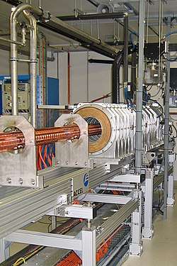
- Extending along the pipe from the source is a series of open-ended cylindrical electrodes (C1, C2, C3, C4), whose length increases progressively with the distance from the source. The particles from the source pass through these electrodes. The length of each electrode is determined by the frequency and power of the driving power source and the particle to be accelerated, so that the particle passes through each electrode in exactly one-half cycle of the accelerating voltage. The mass of the particle has a large effect on the length of the cylindrical electrodes; for example an electron is considerably lighter than a proton and so will generally require a much smaller section of cylindrical electrodes as it accelerates very quickly.
- A target (not shown) with which the particles collide, located at the end of the accelerating electrodes. If electrons are accelerated to produce X-rays then a water cooled tungsten target is used. Various target materials are used when protons or other nuclei are accelerated, depending upon the specific investigation. Behind the target are various detectors to detect the particles resulting from the collision of the incoming particles with the atoms of the target. Many linacs serve as the initial accelerator stage for larger particle accelerators such as synchrotrons and storage rings, and in this case after leaving the electrodes the accelerated particles enter the next stage of the accelerator.
- An electronic oscillator and amplifier (G) which generates a radio frequency AC voltage of high potential (usually thousands of volts) which is applied to the cylindrical electrodes. This is the accelerating voltage which produces the electric field which accelerates the particles. As shown, opposite phase voltage is applied to successive electrodes. A high power accelerator will have a separate amplifier to power each electrode, all synchronized to the same frequency.
As shown in the animation, the oscillating voltage applied to alternate cylindrical electrodes has opposite polarity (180° out of phase), so adjacent electrodes have opposite voltages. This creates an oscillating electric field (E) in the gap between each pair of electrodes, which exerts force on the particles when they pass through, imparting energy to them by accelerating them. The particle source injects a group of particles into the first electrode once each cycle of the voltage, when the charge on the electrode is opposite to the charge on the particles. The electrodes are made the correct length so that the accelerating particles take exactly one-half cycle to pass through each electrode. Each time the particle bunch passes through an electrode, the oscillating voltage changes polarity, so when the particles reach the gap between electrodes the electric field is in the correct direction to accelerate them. Therefore the particles accelerate to a faster speed each time they pass between electrodes; there is little electric field inside the electrodes so the particles travel at a constant speed within each electrode.
The particles are injected at the right time so that the oscillating voltage differential between electrodes is maximum as the particles cross each gap. If the peak voltage applied between the electrodes is volts, and the charge on each particle is elementary charges, the particle gains an equal increment of energy of electron volts when passing through each gap. Thus the output energy of the particles is


electron volts, where is the number of accelerating electrodes in the machine.

At speeds near the speed of light, the incremental velocity increase will be small, with the energy appearing as an increase in the mass of the particles. In portions of the accelerator where this occurs, the tubular electrode lengths will be almost constant. Additional magnetic or electrostatic lens elements may be included to ensure that the beam remains in the center of the pipe and its electrodes. Very long accelerators may maintain a precise alignment of their components through the use of servo systems guided by a laser beam.
Advantages
The linear accelerator could produce higher particle energies than the previous electrostatic particle accelerators (the Cockcroft-Walton accelerator and Van de Graaff generator) that were in use when it was invented. In these machines, the particles were only accelerated once by the applied voltage, so the particle energy in electron volts was equal to the accelerating voltage on the machine, which was limited to a few million volts by insulation breakdown. In the linac, the particles are accelerated multiple times by the applied voltage, so the particle energy is not limited by the accelerating voltage.
High power linacs are also being developed for production of electrons at relativistic speeds, required since fast electrons traveling in an arc will lose energy through synchrotron radiation; this limits the maximum power that can be imparted to electrons in a synchrotron of given size. Linacs are also capable of prodigious output, producing a nearly continuous stream of particles, whereas a synchrotron will only periodically raise the particles to sufficient energy to merit a "shot" at the target. (The burst can be held or stored in the ring at energy to give the experimental electronics time to work, but the average output current is still limited.) The high density of the output makes the linac particularly attractive for use in loading storage ring facilities with particles in preparation for particle to particle collisions. The high mass output also makes the device practical for the production of antimatter particles, which are generally difficult to obtain, being only a small fraction of a target's collision products. These may then be stored and further used to study matter-antimatter annihilation.
Medical linacs
Linac-based radiation therapy for cancer treatment began with the first patient treated in 1953 in London, UK, at the Hammersmith Hospital, with an 8 MV machine built by Metropolitan-Vickers and installed in 1952, as the first dedicated medical linac.[3][4] A short while later in 1954, a 6 MV linac was installed in Stanford, USA, which began treatments in 1956.
Medical grade linacs accelerate electrons using a tuned-cavity waveguide, in which the RF power creates a standing wave. Some linacs have short, vertically mounted waveguides, while higher energy machines tend to have a horizontal, longer waveguide and a bending magnet to turn the beam vertically towards the patient. Medical linacs use monoenergetic electron beams between 4 and 25 MeV, giving an X-ray output with a spectrum of energies up to and including the electron energy when the electrons are directed at a high-density (such as tungsten) target. The electrons or X-rays can be used to treat both benign and malignant disease. The LINAC produces a reliable, flexible and accurate radiation beam. The versatility of LINAC is a potential advantage over cobalt therapy as a treatment tool. In addition, the device can simply be powered off when not in use; there is no source requiring heavy shielding – although the treatment room itself requires considerable shielding of the walls, doors, ceiling etc. to prevent escape of scattered radiation. Prolonged use of high powered (>18 MeV) machines can induce a significant amount of radiation within the metal parts of the head of the machine after power to the machine has been removed (i.e. they become an active source and the necessary precautions must be observed).
Application for medical isotope development
The expected shortages with regard to Mo-99, and the technetium-99m medical isotope obtained from it, has also shed light onto linear accelerator technology to produce Mo-99 from non-enriched Uranium-235 through neutron bombardment. This would enable the medical isotope industry to manufacture this crucial isotope by a sub-critical process. The aging facilities, for example the Chalk River Laboratories in Ontario Canada, which still now produce most Mo-99 from highly enriched Uranium-235 could be replaced by this new process. In this way, the sub-critical loading of soluble uranium salts in heavy water with subsequent photo neutron bombardment and extraction of the target product, Mo-99, will be achieved.[5]
Disadvantages
- The device length limits the locations where one may be placed.
- A great number of driver devices and their associated power supplies are required, increasing the construction and maintenance expense of this portion.
- If the walls of the accelerating cavities are made of normally conducting material and the accelerating fields are large, the wall resistivity converts electric energy into heat quickly. On the other hand, superconductors also need constant cooling to keep them below their critical temperature, and the accelerating fields are limited by quenches. Therefore, high energy accelerators such as SLAC, still the longest in the world (in its various generations), are run in short pulses, limiting the average current output and forcing the experimental detectors to handle data coming in short bursts.
See also
- Accelerator physics
- Beamline
- Compact Linear Collider
- Dielectric wall accelerator
- Duoplasmatron
- International Linear Collider
- Particle accelerator
- Particle beam
- SLAC National Accelerator Laboratory
References
- G. Ising: Prinzip einer Methode zur Herstellung von Kanalstrahlen hoher Voltzahl. In: Arkiv för Matematik, Astronomi och Fysik. Band 18, Nr. 30, 1924, S. 1–4.
- Widerøe, R. (17 December 1928). "Über Ein Neues Prinzip Zur Herstellung Hoher Spannungen". Archiv für Elektronik und Übertragungstechnik. 21 (4): 387–406. doi:10.1007/BF01656341.
- Thwaites, DI and Tuohy J, Back to the future: the history and development of the clinical linear accelerator, Phys. Med. Biol. 51 (2006) R343–R36, doi:10.1088/0031-9155/51/13/R20
- LINAC-3, Advances in Medical Linear Accelerator Technology. ampi-nc.org
- Gahl and Flagg (2009).Solution Target Radioisotope Generator Technical Review. Subcritical Fission Mo99 Production. Retrieved 6 January 2013.
External links
| Wikimedia Commons has media related to Linear particle accelerators. |