Cephalometric analysis
Cephalometric analysis is the clinical application of cephalometry. It is analysis of the dental and skeletal relationships of a human skull.[1] It is frequently used by dentists, orthodontists, and oral and maxillofacial surgeons as a treatment planning tool.[2] Two of the more popular methods of analysis used in orthodontology are the Steiner analysis (named after Cecil C. Steiner) and the Downs analysis (named after William B. Downs).[3] There are other methods as well which are listed below.[4]
Cephalometric radiographs
Cephalometric analysis depends on cephalometric radiography to study relationships between bony and soft tissue landmarks and can be used to diagnose facial growth abnormalities prior to treatment, in the middle of treatment to evaluate progress, or at the conclusion of treatment to ascertain that the goals of treatment have been met.[5] A Cephalometric radiograph is a radiograph of the head taken in a Cephalometer (Cephalostat) that is a head-holding device introduced in 1931 by Holly Broadbent Sr. in USA.[6] The Cephalometer is used to obtain standardized and comparable craniofacial images on radiographic films.
Lateral cephalometric radiographs
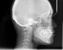
Lateral cephalometric radiograph is a radiograph of the head taken with the x-ray beam perpendicular to the patient's sagittal plane. Natural head position is a standardized orientation of the head that is reproducible for each individual and is used as a means of standardization during analysis of dentofacial morphology both for photos and radiographs. The concept of natural head position was introduced by Coenraad Moorrees and M. R Kean in 1958[7][8] and now is a common method of head orientation for cephalometric radiography.[9][10]
Registration of the head in its natural position while obtaining a cephalogram has the advantage that an extracranial line (the true vertical or a line perpendicular to that) can be used as a reference line for cephalometric analysis, thus bypassing the difficulties imposed by the biologic variation of intracranial reference lines. True vertical is an external reference line, commonly provided by the image of a free-hanging metal chain on the cephalostat registering on the film or digital cassette during exposure. The true vertical line offers the advantage of no variation (since it is generated by gravity) and is used with radiographs obtained in natural head position.
Posteroanterior (P-A) cephalometric radiograph
A radiograph of the head taken with the x-ray beam perpendicular to the patient’s coronal plane with the x-ray source behind the head and the film cassette in front of the patient’s face.[11] PA ceph can be evaluated by following analyses that have been developed through the years:
- Grummon analysis
- MSR
- Hewitt analysis
- Svanholt-Solow analysis
- Grayson analysis
Cephalometric tracing
A Cephalometric tracing is an overlay drawing produced from a cephalometric radiograph by digital means and a computer program or by copying specific outlines from it with a lead pencil onto acetate paper, using an illuminated view-box. Tracings are used to facilitate cephalometric analysis, as well as in superimpositions, to evaluate treatment and growth changes. Historically, tracings of the cephalometric radiographs are done on an 0.003 inch thick matte acetate paper by using a #3 pencil. The process is started by marking three registration crosses on the radiograph which are then transferred to the acetate paper.
Anatomical structures are traced first and some structures are bilateral and have tendency to show up as two separate lines, should have an "average" line drawn which is represented as a broken line. These landmarks could include inferior border of mandible.
Cephalometric landmarks
The following are important cephalometric landmarks, which are points of reference serving as datums in measurement and analysis. (Sources: Proffit;[12] others.)
Landmark points can be joined by lines to form axes, vectors, angles, and planes (a line between 2 points can define a plane by projection). For example, the sella (S) and the nasion (N) are points that together form the sella-nasion line (SN or S-N), which can be projected into the SN plane. A prime symbol (′) usually indicates the point on the skin's surface that corresponds to a given bony landmark (for example, nasion (N) versus skin nasion (N′).
| Landmark name | Landmark symbol | Comments |
|---|---|---|
| A point (subspinale) | A | Most concave point of anterior maxilla |
| A point–nasion–B point angle | ANB | Average of 2° ± 2° |
| B point (supramentale) | B | Most concave point on mandibular symphysis |
| basion | Ba | Most anterior point on foramen magnum |
| anterior nasal spine | ANS | Anterior point on maxillary bone |
| articulare | Ar | Junction between inferior surface of the cranial base and the posterior border of the ascending rami of the mandible |
| Bolton point | Point at the intersection of the occipital condyle and Foramen Magnum at the highest notch posterior to the occipital condyle | |
| cheilion | Ch | Corner of oral cavity |
| chresta philtri | Chp | Head of nasal filter |
| condylion | Most posterior/superior point on the condyle of mandible | |
| dacryon | dac | Point of junction of maxillary bone, lacrimal bone, and frontal bone |
| endocanthion | En | Point at which inner ends of upper and lower eyelids meet (medial canthal point) |
| exocanthion (synonym, ectocanthion) | Ex | Point at which outer ends of upper and lower eyelids meet (lateral canthal point) |
| frontotemporal | Ft | Most medial point on the temporal crest |
| glabella | G' | Most prominent point in the median sagittal plane between the supraorbital ridges |
| gnathion | Gn | Point located perpendicular on mandibular symphysis midway between pogonion and menton |
| gonion | Go | Most posterior inferior point on angle of mandible. Can also be constructed by bisecting the angle formed by intersection of mandibular plane and ramus of mandible |
| key ridges | Posterior vertical portion and inferior curvature of left and right zygomatic bones | |
| labial inferior | Li | Point denoting vermilion border of lower lip in midsagittal plane |
| labialis superior | Ls | Point denoting vermilion border of upper lip |
| lower incisor | L1 | Line connecting incisal edge and root apex of the most prominent mandibular incisor |
| menton | Me | Lowest point on mandibular symphysis |
| soft tissue menton | Me′ | Lowest point on soft tissue over mandible |
| nasion | N | Most anterior point on frontonasal suture |
| soft tissue nasion | N′ | Point on soft tissue over nasion |
| odontale | Highest point on second vertebra | |
| orbitale | Or | Most inferior point on margin of orbit |
| opisthion | Op | Most posterior point of foramen magnum |
| pogonion | Pg | Most anterior point of mandibular symphysis |
| soft tissue pogonion | Pg′ | Soft tissue over pogonion |
| porion | Po | Most superior point of outline of external auditory meatus |
| machine porion | Superior-most point of the image of the ear rod | |
| posterior nasal spine | PNS | Posterior limit of bony palate or maxilla |
| pronasale (synonyms, pronasal or pronasion) | Prn | Soft tissue point on tip of nose |
| prosthion (supradentale, superior prosthion) | Pr | The most inferior anterior point on the maxillary alveolar process between the central incisors |
| PT point | PT | Point at junction between Ptm and foramen rotundum (at 11 o'clock from Ptm) |
| pterygomaxillary fissure | Ptm | Point at base of fissure where anterior and posterior wall meet. Anterior wall represents posterior surface of maxillary tuberosity |
| registration point | A reference point for superimposition of ceph tracings | |
| sella (that is, sella turcica) | S | Midpoint of sella turcica |
| sphenoethmoidal suture | SE | the cranial suture between the sphenoid bone and the ethmoid bone |
| sella–nasion line | SN or S-N | Line from sella to nasion |
| sella–nasion–A point angle | SNA or S-N-A | Average of 82 degrees with +/- of 2 degrees |
| sella–nasion–B point angle | SNB or S-N-B | Average of 80 degrees with +/- of 2 degrees |
| sublabialis | Sl | |
| subnasale (synonyms, subnasal or subnasion) | Sn | In the midline, the junction where base of the columella of the nose meets the upper lip |
| stomion inferius | Sti | Highest midline point of lower lip |
| stomion superius | Sts | Highest midline point of upper lip |
| throat point | Junction of inferior border of mandible and throat | |
| tragion | T′ | Notch above the tragus of the ear where the upper edge of the cartilage disappears into the skin of the face |
| trichion | Tr | Midline of hairline |
| upper incisor | U1 | A line connecting the incisal edge and root apex of the most prominent maxillary incisor |
| xi point | Xi | An approximate point for inferior alveolar foramen |
Below is a list of cephalometric planes that are commonly used in different cephalometric analyses.
| Cephalometric plane | Plane symbol | Definition |
|---|---|---|
| palatal plane | ANS-PNS | This plane is formed by connecting ANS to PNS and is used to measure the vertical tilt of maxilla |
| SN plane | SN plane | This plane represents the anterior cranial base and is formed by projecting a plane from the sella-nasion line |
| Frankfort horizontal plane (Frankfurt horizontal plane) | P-Or | This plane represents the habitual postural position of the head. |
| condylar plane | Co-Or | This plane can be used as an alternate to Frankfort horizontal plane. |
| functional occlusal plane | FOP | This plane passes is formed by drawing a line that touches the posterior premolars and molars. |
| Downs occlusal plane | DOP | This plane is formed by bisecting the anterior incisors and the distal cusps of the most posterior in occlusion. |
| mandibular plane | Go-Gn | This plane is formed by connecting the point gonion to gnathion at the inferior border of the mandible. |
| facial plane | N-Pg | This vertical plane is formed by connecting nasion to pogonion as described in the Schudy analysis. |
| Bolton plane | Bolton Pt-N | This plane is formed by connecting the Bolton point to nasion. This plane includes the registration point and is part of the Bolton triangle. |
Classification of analyses
The basic elements of analysis are angles and distances. Measurements (in degrees or millimetres) may be treated as absolute or relative, or they may be related to each other to express proportional correlations. The various analyses may be grouped into the following:
- Angular – dealing with angles,
- Linear – dealing with distances and lengths,
- Coordinate – involving the Cartesian (X, Y) or even 3-D planes,
- Arcial – involving the construction of arcs to perform relational analyses.
These in turn may be grouped according to the following concepts on which normal values have been based:
- Mononormative analyses: averages serve as the norms for these and may be arithmetical (average figures) or geometrical (average tracings). E.g. Bolton Standards.
- Multinormative: for these a whole series of norms are used, with age and sex taken into account, e.g. Bolton Standards.
- Correlative: used to assess individual variations of facial structure to establish their mutual relationships, e.g. the Sassouni arcial analysis.
Cephalometric angles
According to the Steiner analysis:
- ANB (A point, nasion, B point) indicates whether the skeletal relationship between the maxilla and mandible is a normal skeletal class I (+2 degrees), a skeletal Class II (+4 degrees or more), or skeletal class III (0 or negative) relationship.
- SNA (sella, nasion, A point) indicates whether or not the maxilla is normal, prognathic, or retrognathic.
- SNB (sella, nasion, B point) indicates whether or not the mandible is normal, prognathic, or retrognathic.
SNA and SNB is important to determine what type of intervention (on maxilla, mandible or both) is appropriate. These angles, however are influenced also by the vertical height of the face and a possible abnormal positioning of nasion.[12] By using a comparative set of angles and distances, measurements can be related to one another and to normative values to determine variations in a patient’s facial structure.[13]
Analyses (analytic approaches) by various authors
Steiner analysis
Cecil C. Steiner developed Steiner Analysis in 1953. He used S-N plane as his reference line in comparison to FH plane due to difficulty in identifying the orbitale and porion. Some of the drawbacks of the Steiner analysis includes its reliability on the point nasion. Nasion as a point is known not to be stable due to its growth early in life. Therefore, a posteriorly positioned nasion will increase ANB and more anterior positioned nasion can decrease ANB. In addition, short S-N plane or stepper S-N plane can also lead to greater numbers of SNA, SNB and ANB which may not reflex the true position of the jaws compare to the cranial base. In addition, clockwise rotation of both jaws can increase ANB and counter-clockwise rotation of jaws can decrease ANB.
| Name | Description | Normal | Standard Deviation |
|---|---|---|---|
| Skeletal | |||
| SNA (°) | Sella-Nasion to A Point Angle | 82 degrees | +/- 2 |
| SNB (°) | Sella-Nasion to B Point Angle | 80 degrees | +/- 2 |
| ANB (°) | A point to B Point Angle | 2 degrees | +/- 2 |
| Occlusal Plane to SN (°) | SN to Occlusal Plane Angle | 14 degrees | |
| Mandibular Plane (°) | SN to Mandibular Plane Angle | 32 degrees | |
| Dental | |||
| U1-NA (degree) | Angle between upper incisor to NA line | 22 degrees | |
| U1-NA (mm) | Distance from upper incisor to NA line | 4 mm | |
| L1-NB (degree) | Angle between lower incisor to NB line | 25 degrees | |
| L1-NB (mm) | Distance from lower incisor to NB line | 4 mm | |
| U1-L1 (°) | Upper incisor to lower incisor angle | 130 degrees | |
| L1-Chin (mm) | Also known as Holdaway Ratio. It states that chin prominence should be as far away as the farthest point of the lower incisor should be. An ideal distance is 2mm from Pogonion to NB line and L1 to NB line. | 4mm | |
| Soft tissue | |||
| S Line | Line formed by connecting Soft Tissue Pogonion and middle of an S formed by lower border of the nose | Ideally, both lips should touch the S line |
Wits analysis
The name Wits is short for Witwatersrand, which is a University in South Africa. Jacobsen in 1975 published an article called "The Wits appraisal of jaw disharmony".[14] This analysis was created as a diagnostic aid to measure the disharmony between the AP degree. The ANB angle can be affected by multitude of environmental factors such as:
- Patient's age where ANB has tendency to reduced with age
- Change in position of nasion as pubertal growth takes place
- Rotational effect of jaws
- Degree of facial Prognathism
Therefore, it measured the AP positions of the jaw to each other. This analysis calls for 1. Drawing an Occlusal Plane through the overlapping cusps of Molars and Premolars. 2. Draw perpendicular lines connecting A point and B Point to the Occlusal Plane 3. Label the points as AO and BO.[15]
In his study, Jacobsen mentioned that average jaw relationship is -1mm in Males (AO is behind BO by 1mm) and 0mm in Females (AO and BO coincide). Its clinical significance is that in a Class 2 skeletal patient, AO is located ahead of BO. In skeletal Class 3 patient, BO is located ahead of AO. Therefore, the greater the wits reading, the greater the jaw discrepancy.
Drawbacks to Wits analysis includes:[16]
- Left and Right molar outlines may not always coincide
- Occlusal plane may differ in mixed vs permanent dentition
- If curve of spee is deep then it may be difficult to create a straight occlusal plane
- Angulation of functional occlusal plane to pterygomaxillary vertical plane was shown to decrease from age 4 to 24.
Downs analysis
| Name | Description | Normal | Standard Deviation |
|---|---|---|---|
| Skeletal | |||
| Facial Angle (°) | Angle between Nasion-Pogonion and Frankfurt Horizontal Line | 87.8 | +/- 3.6 |
| Angle of Convexity (°) | Angle between Nasion - A point and A point - Pogonion Line | 0 | +/- 5.1 |
| Mandibular Plane Angle (°) | Angle between Frankfort horizontal line and the line intersecting Gonion-Menton | 21.9 | +/- 5 |
| Y Axis (°) | Sella Gnathion to Frankfurt Horizontal Plane | 59.4 | +/- 3.8 |
| A-B Plane Angle (°) | Point A-Point B to Nasion-Pogonion Angle | -4.6 | +/- 4.6 |
| Dental | |||
| Cant of Occlusal Plane (°) | Angle of cant of occlusal plane in relation to FH Plane | 9.3 | +/- 3.8 |
| Inter-Incisal Angle (°) | 135.4 | +/- 5.8 | |
| Incisor Occlusal Plane Angle (°) | Angle between line through long axis of Lower Incisor and occlusal Plane | 14.5 | +/- 3.5 |
| Incisor Mandibular Plane Angle (°) | Angle between line through long axis of Lower incisor and Mandibular Plane | 1.4 | +/- 3.8 |
| U1 to A-Pog Line (mm) | 2.7 | +/- 1.8 |
Bjork analysis
This analysis by Arne Bjork was developed in 1947 based on 322 Swedish boys and 281 conscripts. He introduced a facial polygon which was based on 5 angles and is listed below. Bjork also developed the 7 structural signs which indicates the mandibular rotator type.[17]
- Nasion Angle - Formed by line connecting ANS to Nasion to Sella
- Saddle or Cranial Base Angle - Formed by line connecting Nasion to Sella to Articulare
- Articular Angle - Formed by line connecting Sella to Articulare to Gonion
- Gonial Angle - Formed by line connecting Articulare to Gonion to Gnathion
- Chin Angle - Formed by line connecting Infradentale to Pogonion to the Mandibular Plane.
Tweed analysis (triangle)
Charles H. Tweed developed his analysis in the year 1966.[18] In this analysis, he tried describing the lower incisor position in relation to the basal bone and the face. This is described by 3 planes. He used Frankfurt Horizontal plane as a reference line.[19][20]
| Name | Description | Normal |
|---|---|---|
| Tweed facial triangle | ||
| IMPA (°) | Angle between long axis of lower incisor and mandibular plane angle | 90 (°) +/- 5 |
| FMIA (°) | Frankfort mandibular incisor angle | 65 (°) |
| FMA (°) | Frankfort mandibular plane angle | 25 (°) |
| Total | 180 (°) |
Jarabak analysis
Analysis developed by Joseph Jarabak in 1972.[21] The analysis interprets how the craniofacial growth may affect the pre and post treatment dentition. The analysis is based on 5 points: Nasion (Na), Sella (S), Menton (Me), Go (Gonion) and Articulare (Ar). They together make a Polygon on a face when connected with lines. These points are used to study the anterior/posterior facial height relationships and predict the growth pattern in the lower half of the face. Three important angles used in his analysis are: 1. Saddle Angle - Na, S, Ar 2. Articular Angle - S-Ar-Go, 3. Gonial Angle - Ar-Go-Me.
In a patient who has a clockwise growth pattern, the sum of 3 angles will be higher than 396 degrees. The ratio of posterior height (S-Go) to Anterior Height (N-Me) is 56% to 44%. Therefore, a tendency to open bite will occur and a downward, backward growth of mandible will be observed.[22]
Ricketts analysis
| Landmark Name | Landmark Symbol | Description |
|---|---|---|
| Upper Molar | A6 | Point on the occlusal plane located perpendicular to the distal surface of the crown of the upper first molar |
| Lower Molar | B6 | Point on the occlusal plane located perpendicular to the distal surface of the crown of the lower first molar |
| Condyle | CI | A point on the condyle head in contact with and tangent to the ramus plane |
| Soft Tissue | DT | Point on the anterior curve of the soft tissue chin tangent to the esthetic plane or E line |
| Center of Cranium | CC | Point of intersection of the basion-nasion plane and the facial axis |
| Points from Plane at Pterygoid | CF | The point of intersection of the pterygoid root vertical to the Frankfort horizontal plane |
| PT Point | PT | Junction of Pterygomaxillary fissure and the foramen rotundum. |
| Condyle | DC | Point in the center of the condyle neck along the Ba-N plane |
| Nose | En | Point on the soft tissue nose tangent to the esthetic plane |
| Gnathion | Gn | Point of intersection between the line between pogonion and menton |
| Gonion | Go | Point of intersection between ramus plane and mandibular plane |
| Suprapogonion | PM | Point at which shape of symphysis mentalis changes from convex to concave |
| Pogonion | Pog | Most anterior point of the mandibular symphysis |
| Cephalometric | PO | Intersection of facial plane and corpus axis |
| T1 Point | TI | Point of intersection of the occlusal and facial planes |
| Xi Point | Xi | |
| Name of Planes | Symbol | |
| Frankfort Horizontal | FH Plane | This plane extends from porion to orbitale |
| Facial Plane | This plane extends from nasion to pogonion | |
| Mandibular Plane | Plane extending from gonion to gnathion | |
| PtV (Pterygoid vertical) | This line is drawn through PTM and is perpendicular to the FH plane | |
| Basion-Nasion Plane | Plane extending from basion to nasion | |
| Occlusal Plane | Occlusal plane through molars and premolars contact (functional plane) | |
| A-Pog Line | A line extending from Point A to pogonion | |
| E-Line | This line extends from the tip of soft tissue nose to soft tissue Pogonion |
The Rickett analysis also consists of following measurements
| Name | Description | Normal | Standard Deviation |
|---|---|---|---|
| Facial Axis | Angle between Pt/Gn and the line N/Ba | 90 | +/- 3.5 |
| Facial Angle | Angle between the line FL and FH | 89 | +/- 3 |
| ML/FH | Angle between the line FH and the line ML | 24 | +/- 4.5 |
| Convexity | Distance between Pog/N and A | 0 | +/- 2 |
| Li-A-Pog | Distance between Pog/A and Li | 1 | +/- 2 |
| Ms-PtV | Projection on the line FH of the distance between the markers PT/Ms-d | 18 | |
| ILi-/A-Pog | Distance between the line Pog/A and the line Lia/Li | 22 | +/- 4 |
| Li-EL | Distance between the line EL and Li | -2 | +/- 2 |
Sassouni analysis
This analysis, developed by Viken Sassouni in 1955,[23][24] states that in a well proportioned face, the following four planes meet at the point O. The point O is located in the posterior cranial base.This method categorized the vertical and the horizontal relationship and the interaction between the vertical proportions of the face.The planes he created are:
- Supraorbital plane (anterior clenoid to roof of orbits)
- Palatal plane (ANS-PNS)
- Occlusal plane (Downs occlusal plane)
- Mandibular plane (Go-Me)
The more parallel the planes, the greater the tendency for deep bite and the more non-parallel they are the greater the tendency for open bite. Using the O as the centre, Sassouni created the following arcs
- Anterior Arc - Arc of a circle between the anterior cranial base and the mandibular plane, with O as the center and O-ANS as the radius.
- Posterior Arc - Arc of a circle between anterior cranial base and mandibular base with O as centre and OSp as radius.
- Basal Arc - From A point should pass through B point
- Midfacial Arc - From Te and should pass tangent to the mesial surface of the maxillary first molar
Harvold analysis
This analysis was developed by Egil Peter Harvold in 1974.[25] This analysis developed standards for the unit length of the maxilla and mandible. The difference between the unit length describes the disharmony between the jaws. It is important to know that location of teeth is not taken into account in this analysis.
The maxillary unit length is measured from posterior border of mandibular condyle (Co) to ANS. The mandibular unit length is measured from posterior border of mandibular condyle (Co) to Pogonion. This analysis also looks at the lower facial height which is from upper ANS to Menton.[26]
McNamara analysis
| Landmark Name | Landmark Symbol | Description | Normal |
|---|---|---|---|
| Maxilla to Cranial Base | |||
| Nasolabial Angle | 14 degrees | ||
| Na Perpendicular to Point A | 0-1mm | ||
| Maxilla to Mandible | |||
| AP | |||
| Mandibular Length (Co-Gn) | |||
| Mandible to Cranial Base | |||
| Pog-Na Perpendicular | Small = -8 to -6mm
Medium = -4mm to 0mm Large = -2mm to +2mm | ||
| Dentition | |||
| 1 to A-Po | 1-3mm | ||
| 1 to Point A | 4-6mm | ||
| Airway | |||
| Upper Pharynx | 15-20mm | ||
| Lower Pharynx | 11-14mm |
COGS analysis (cephalometrics for orthognathic surgery)
This analysis was developed by Charles J. Burstone when it was presented in 1978 in an issue of AJODO.[27] This was followed by Soft Tissue Cephalometric Analysis for Orthognathic Surgery in 1980 by Arnette et al.[28] In this analysis, Burstone et al. used a plane called horizontal plane, which was a constructed of Frankfurt Horizontal Plane.
| Landmark Name | Landmark Symbol | Description | Normal |
|---|---|---|---|
| Cranial Base | |||
| Posterior Cranial Base | AR-PTM | ||
| Anterior Cranial BAse | PTM-N | ||
| Vertical Skeletal and Dental | |||
| Upper Anterior Facial Height | N-ANS | ||
| Lower Anterior Facial Height | ANS-GN | ||
| Upper Posterior Facial Height | PNS-N | ||
| Mandibular Plane Angle | MP-HP | ||
| Upper Anterior Dental Height | U1-NF | ||
| Lower Anterior Dental Height | L1-MP | ||
| Upper Posterior Dental Height | UM-NF | ||
| Lower Posterior Dental Height | LM-MP | ||
| Maxilla and Mandible | |||
| Maxillary Length | PNS-ANS | ||
| Mandibular Ramus Length | |||
| Mandibular Body Length | |||
| Chin Depth | B-PG | ||
| Gonial Angle | AR-GO-GN | ||
| Dental Relationships | |||
| Occlusal Plane | OP-HP | ||
| Upper incisors inclination | U1-NF | ||
| Lower incisors inclination | L1/GO-ME | ||
| Wits Analysis | A-B/OP |
- Counterpart Analysis
- Template Analysis
Computerised cephalometrics
Computerised cephalometrics is the process of entering cephalometric data in digital format into a computer for cephalometric analysis. Digitization (of radiographs) is the conversion of landmarks on a radiograph or tracing to numerical values on a two- (or three-) dimensional coordinate system, usually for the purpose of computerized cephalometric analysis. The process allows for automatic measurement of landmark relationships. Depending on the software and hardware available, the incorporation of data can be performed by digitizing points on a tracing, by scanning a tracing or a conventional radiograph, or by originally obtaining computerized radiographic images that are already in digital format, instead of conventional radiographs. Computerized cephalometrics offers the advantages of instant analysis; readily available race-, sex- and age-related norms for comparison; as well as ease of soft tissue change and surgical predictions. Computerized cephalometrics has also helped in eliminating any surgeon inadequacies as well as making the process less time consuming.
The first medically certified automated cephalometric analysis of 2D lateral cephalometric radiographs by Artificial Intelligence was brought to market in November 2019[29].
Digitization
Computer processing of cephalometric radiographs uses a digitizer. Digitization refers to the process of expressing analog information in a digital form. A digitizer is a computer input device which converts analog information into an electronic equivalent in the computer’s memory. In this treatise and its application to computerized cephalometrics, digitization refers to the resolving of headfilm landmarks into two numeric or digital entities – the X and Y coordinate. 3D analysis would have third quantity - Z coordinate.
Superimposition
Cephalometric radiographs can be superimposed on each other to see the amount of growth that has taken place in an individual or to visualize the amount of movement of teeth that has happened in the orthodontic treatment. It is important to superimpose the radiograph on a stable anatomical structures. Traditionally, this process has been done by tracing and superimposing on cranial landmarks. One of the most common used methods of superimposing is called the Structural Method.
Structural method
According to American Board of Orthodontics, this method is based on series of study performed by Arne Bjork,[30][31] Birte Melsen[32] and Donald Enlow.[33] This method divides superimposition in three categories: Cranial base superimposition, maxillary superimposition and mandibular superimposition. Some of the important landmarks in each category is listed below as per the structural method.
Cranial base superimposition
- The inner contour of the anterior wall of sella turcica
- Walker point
- The anterior contour of the middle cranial fossa
- The contour of the cribriform plate
- Details in the trabecular system in the anterior cranial fossa.
- The contours of the bilateral fronto-ethmoidal crests.
- The cerebral surfaces of the orbital roofs
Mandibular superimposition
- The anterior contour of the chin
- The inner cortical structure at the inferior border of the mandibular symphysis.
- Trabecular structures in the mandibular symphysis.
- Trabecular structures related to the mandibular canal.
- The lower contour of a molar germ
Maxillary superimposition
- The anterior contour of the zygomatic process
See also
References
- Centre for Cancer Education, March 5, 2000
- Cephalometric analysis as a tool for treatment planning and evaluation, European Journal of Orthodontics 1981 3(4):241-245
- Oria, A; Schellino, E; Massaglia, M; Fornengo, B (June 1991). "[A comparative evaluation of Steiner's and McNamara's methods for determining the position of the bone bases]". Minerva Stomatol. 40 (6): 381–5. PMID 1944052.
- Evaluating Ricketts' Cephalometric Analysis as Diagnostic Aid in Black Females, Center For the Study of Human Growth and Development April 5, 2008 Archived October 26, 2008, at the Wayback Machine
- Predoctoral Orthodontic Laboratory Manual 2008, Department of Undergraduate Orthodontics, New Jersey Dental School
- US Patent #2032833 by Birdsall H. Broadbent http://www.google.com/patents/US2032833
- Moorrees, Coenraad F. A.; Kean, Martin R. (1958-06-01). "Natural head position, a basic consideration in the interpretation of cephalometric radiographs". American Journal of Physical Anthropology. 16 (2): 213–234. doi:10.1002/ajpa.1330160206. ISSN 1096-8644.
- Moorrees, Coenraad F.A. (1994-05-01). "Natural head position—a revival". American Journal of Orthodontics and Dentofacial Orthopedics. 105 (5): 512–3. doi:10.1016/S0889-5406(94)70014-1. ISSN 0889-5406. PMID 8166103.
- Weber, Diana W.; Fallis, Drew W.; Packer, Mark D. (2013-05-01). "Three-dimensional reproducibility of natural head position". American Journal of Orthodontics and Dentofacial Orthopedics. 143 (5): 738–744. doi:10.1016/j.ajodo.2012.11.026. ISSN 0889-5406. PMID 23631976.
- Bansal, Naveen; Singla, Jeetinder; Gera, Gurmeet; Gupta, Monika; Kaur, Gurpreet (2012). "Reliability of natural head position in orthodontic diagnosis: A cephalometric study". Contemporary Clinical Dentistry. 3 (2): 180–183. doi:10.4103/0976-237X.96824. ISSN 0976-237X. PMC 3425102. PMID 22919219.
- Bergman, R. (March 1988). "Practical applications of the PA cephalometric headfilm". Orthodontic Review. 2 (2): 20–26. ISSN 0895-5034. PMID 3269997.
- Proffit, William R.. Contemporary Orthodontics, 3rd Edition. C.V. Mosby, 012000. 6.4.2.2.2)
- Dory, Miri (March 13, 2014). "Cephalometric analysis", Cephx.
- Jacobson, A. (1975-02-01). "The "Wits" appraisal of jaw disharmony". American Journal of Orthodontics. 67 (2): 125–138. doi:10.1016/0002-9416(75)90065-2. ISSN 0002-9416. PMID 1054214.
- Jacobson, Alex (2009-07-15). "Update on the Wits Appraisal". The Angle Orthodontist. 58 (3): 205–19. doi:10.1043/0003-3219(1988)058<0205:uotwa>2.0.co;2 (inactive 2019-08-20). PMID 3056122.
- Zawawi, Khalid H. (2012-01-01). "Comparison of Wits appraisal among different ethnic groups". Journal of Orthodontic Science. 1 (4): 88–91. doi:10.4103/2278-0203.105874. ISSN 2278-1897. PMC 4072364. PMID 24987633.
- Björk, A. (September 1966). "Sutural growth of the upper face studied by the implant method". Acta Odontologica Scandinavica. 24 (2): 109–127. doi:10.3109/00016356609026122. ISSN 0001-6357. PMID 5225742.
- Greenstein, A. V (1943-09-01). "The tweed philosophy". American Journal of Orthodontics and Oral Surgery. 29 (9): 527–540. doi:10.1016/S0096-6347(43)90310-2.
- Cross, J. J. (December 1996). "The Tweed philosophy: the Tweed years". Seminars in Orthodontics. 2 (4): 231–236. doi:10.1016/s1073-8746(96)80022-3. ISSN 1073-8746. PMID 9161293.
- Vaden, J. L. (December 1996). "The Tweed-Merrifield philosophy". Seminars in Orthodontics. 2 (4): 237–240. doi:10.1016/s1073-8746(96)80023-5. ISSN 1073-8746. PMID 9161294.
- Jarabak, Joseph R.; Fizzell, James A. (1972). Technique and treatment with light-wire edgewise appliances. C. V. Mosby Co. ISBN 9780801624292.
- Rodriguez-Cardenas, Yalil Augusto; Arriola-Guillen, Luis Ernesto; Flores-Mir, Carlos (2014). "Björk-Jarabak cephalometric analysis on CBCT synthesized cephalograms with different dentofacial sagittal skeletal patterns". Dental Press Journal of Orthodontics. 19 (6): 46–53. doi:10.1590/2176-9451.19.6.046-053.oar. ISSN 2176-9451. PMC 4347410. PMID 25628079.
- Sassouni, Viken (1955-10-01). "A roentgenographic cephalometric analysis of cephalo-facio-dental relationships". American Journal of Orthodontics. 41 (10): 735–764. doi:10.1016/0002-9416(55)90171-8. ISSN 0002-9416.
- Phillips, J. G. (August 1978). "Photo-cephalometric analysis in treatment planning for surgical correction of facial disharmonies". Journal of Maxillofacial Surgery. 6 (3): 174–179. doi:10.1016/s0301-0503(78)80087-3. ISSN 0301-0503. PMID 279635.
- Woodside, Donald G. (1975-09-01). "The activator in interceptive orthodontics". American Journal of Orthodontics. 68 (3): 343. doi:10.1016/0002-9416(75)90245-6. ISSN 0002-9416.
- Harvold, Egil P. (1974). The activator in interceptive orthodontics. C. V. Mosby Co. ISBN 9780801620942.
- Burstone, C. J.; James, R. B.; Legan, H.; Murphy, G. A.; Norton, L. A. (April 1978). "Cephalometrics for orthognathic surgery". Journal of Oral Surgery. 36 (4): 269–277. ISSN 0022-3255. PMID 273073.
- Arnett, G. W.; Jelic, J. S.; Kim, J.; Cummings, D. R.; Beress, A.; Worley, C. M.; Chung, B.; Bergman, R. (September 1999). "Soft tissue cephalometric analysis: diagnosis and treatment planning of dentofacial deformity". American Journal of Orthodontics and Dentofacial Orthopedics. 116 (3): 239–253. doi:10.1016/S0889-5406(99)70234-9. ISSN 0889-5406. PMID 10474095.
- Waldraff, Tassilo. "http://www.cellmatiq.com/". Retrieved 2019-11-25. External link in
|title=(help) - Björk, A.; Skieller, V. (February 1983). "Normal and abnormal growth of the mandible. A synthesis of longitudinal cephalometric implant studies over a period of 25 years". European Journal of Orthodontics. 5 (1): 1–46. doi:10.1093/ejo/5.1.1. ISSN 0141-5387. PMID 6572593.
- Björk, A.; Skieller, V. (April 1977). "Growth of the maxilla in three dimensions as revealed radiographically by the implant method". British Journal of Orthodontics. 4 (2): 53–64. doi:10.1179/bjo.4.2.53. ISSN 0301-228X. PMID 273440.
- "The cranial base: The postnatal development of the cranial base studied histologically on human autopsy material". American Journal of Orthodontics. 66 (6): 689–691. 1974-12-01. doi:10.1016/S0002-9416(74)90320-0.
- Enlow, Donald H.; Harris, David B. (1964). "A study of the postnatal growth of the human mandible". American Journal of Orthodontics. 50 (1): 25–50. doi:10.1016/S0002-9416(64)80016-6. ISSN 0002-9416.